


Fillets and chamfers are often treated as small, interchangeable details on a drawing. In practice, they are design decisions with very different consequences. A seemingly minor choice at an edge can determine whether a part machines cleanly, assembles smoothly, or fails earlier than expected. In some cases, it only adds unnecessary costs. In others, it quietly becomes a reliability issue that appears much later in use.
The difference between a fillet and a chamfer is not about appearance. It affects tool access, stress distribution, edge durability, and how forgiving a part is during assembly.
This article looks at fillets and chamfers from a manufacturing point of view and explains when each one makes sense, what problems they solve, and what often goes wrong when they are used without a clear purpose.
1. Why Fillets and Chamfers Matter in Engineering Design

Fillets and chamfers may seem like minor details on a drawing, but they directly affect how parts are machined, assembled, and performed in service. Choosing the wrong option can increase machining time, complicate assembly, or reduce part durability.
Machining Considerations
Sharp corners limit tool access and often require extra operations or smaller cutters. Fillets help distribute stress and allow smoother machining, while chamfers provide clean lead-ins for cutting tools.
Assembly Efficiency
Chamfers guide parts into position, prevent fasteners from catching, and protect mating surfaces. Fillets reduce interference between components and make handling easier during assembly.
Material Performance
In plastics, sharp corners can trap material and concentrate stress, leading to cracks or sink marks. In sheet metal, appropriate radii and chamfers improve bend quality and reduce sharp edges that could cause handling or safety issues.
Fillets and chamfers are small, but selecting the right one can make machining faster, assembly smoother, and parts more reliable in the long term.
2. What Is a Fillet?

A fillet replaces a sharp corner with a smooth, continuous radius. Its defining parameter is the radius (R), which determines how gradual the transition is between adjoining surfaces.
From a manufacturing perspective, fillets serve several critical functions:
- Reduce stress concentration: A fillet distributes stress along the curved edge, eliminating sharp points that could initiate cracks or premature failure under load.
- Improve fatigue resistance: By smoothing transitions, fillets allow parts to withstand repeated forces and vibrations more reliably over time.
- Guide tooling and mold design: Producing fillets requires radius-capable tools in CNC machining or carefully designed cavity shapes in injection molding to ensure the radius is consistent and accurate.
While larger radii further reduce stress concentration, they can also increase machining time, require larger tooling, or interfere with mating components.
3. What Is a Chamfer?
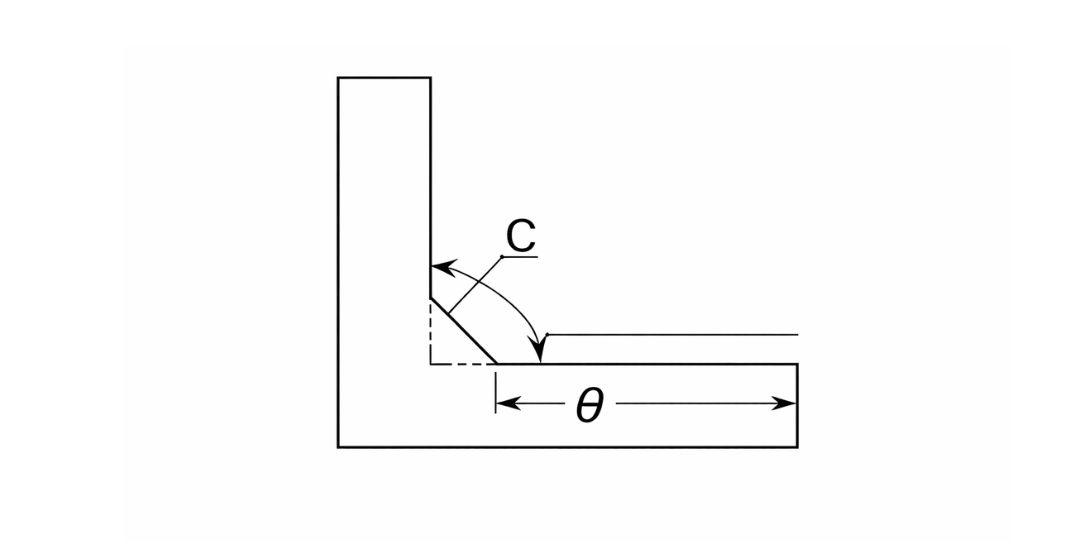
A chamfer removes a sharp corner by cutting a flat surface at an angle, most commonly 45 degrees. Its defining parameters are the chamfer width (C) and the angle, which together determine the size and slope of the beveled edge.
Chamfers are typically specified in drawings as
- C1 × 45°: a 1 mm wide chamfer at a 45-degree angle.
- 2 × 45°: a 2 mm wide chamfer at 45 degrees.
- Width × width: equal chamfers on both adjoining surfaces, creating a symmetrical beveled edge.
From a functional standpoint, chamfers provide several advantages:
- Guide assembly: The angled edge helps parts align more easily during assembly, reducing the risk of interference and speeding up the process.
- Remove burrs: Chamfering eliminates sharp material edges left by cutting, drilling, or stamping, improving part safety and surface quality.
- Protect mating surfaces: The beveled edge prevents damage to adjacent parts or fasteners by softening contact points and reducing wear.
Chamfers are simple in shape but play a crucial role in improving assembly efficiency, reducing post-processing work, and protecting both parts and tools.
4. Key Technical Differences: Fillet and Chamfer
Fillets and chamfers differ in geometry, parameters, and function, and each is suited to specific machining and assembly needs. The table below summarizes their key technical distinctions:
| Özellik | Fillet | Chamfer |
| Geometry | Smooth radius | Flat angled surface |
| Main parameter | Radius (R) | Width (C) + Angle (°) |
| Stress concentration | Çok düşük | Reduced, but higher than fillet |
| Machining complexity | Medium to high | Low to medium |
| Typical applications | Load-bearing areas, flow paths | Assembly edges, deburring |
| Material removal | Higher (especially large radii) | Daha düşük |
Fillets are ideal where stress reduction and mechanical performance matter, while chamfers are preferred for assembly guidance, burr removal, and protecting mating surfaces. Selecting the right feature requires balancing part function, manufacturability, and assembly efficiency.
5. Manufacturing Processes: How Fillets and Chamfers Are Made

The feasibility and cost of fillets and chamfers depend on material, tolerance, and production volume. Different manufacturing methods are better suited for each feature, as summarized below:
Fillet Manufacturing Methods
- CNC Machining: Fillets in metal and rigid plastic parts are created using radius-capable tools or multi-axis tool paths. Larger radii and tighter tolerances increase cycle time.
- Injection or Compression Molding: Fillets can be designed directly into molds. In plastic parts, they reduce internal stress, improve mold filling, and enhance part strength.
- Manual Grinding and Polishing: Suitable for low-volume production or post-processing corrections, but not recommended for precision-critical fillets.
- Laser or Waterjet Cutting: Can form fillets on certain profiles, though internal fillets are limited by cutting physics.
Chamfer Manufacturing Methods
- CNC Turning and Milling: Chamfers are easy to machine with standard tools and short cycle times.
- Drilling and Countersinking: Effective for hole edges, guiding fastener installation and protecting threads.
- Sheet Metal Stamping: Chamfers can be integrated into dies for high-volume production.
- Manual Deburring: Used for simple parts or secondary finishing operations.
How to Choose the Right Process
| Faktör | Recommended Method |
| High precision | CNC machining or electrochemical processes |
| High production volume | Injection molding (fillets) or stamping (chamfers) |
| Short lead time | CNC or manual operations |
| Material consideration | Plastics favor molded fillets; metals favor machined chamfers |
Fillets generally require more complex tooling but provide mechanical and flow benefits, while chamfers are simpler to produce and improve assembly, burr removal, and surface protection. Selecting the right method ensures optimal part performance, manufacturability, and cost efficiency.
6. Functional Roles of Fillets and Chamfers in Real Applications
Fillets and chamfers serve distinct purposes, and using each in the right context improves performance and assembly.
What Fillets Do Best
Fillets are used where smooth transitions and stress relief are needed:
- Reduce stress concentration: Smooth radii at internal corners prevent sharp stress risers, extending part life.
- Improve fatigue life: Components with fillets withstand cyclic loading better.
- Enhance safety: Rounded edges eliminate sharp corners that could cause injury or damage.
- Optimize fluid or air flow: Fillets create smoother channels in ducts, pipes, and pump housings.
What Chamfers Do Best
Chamfers are ideal where assembly and surface protection are priorities:
- Guide parts during assembly: Angled edges help components align quickly and accurately.
- Remove burrs: Chamfers eliminate sharp edges left from cutting, stamping, or drilling.
- Protect mating surfaces and fasteners: Beveled edges prevent scratches or interference during assembly.
- Improve positional alignment: Chamfers assist in precise positioning in tight or high-accuracy assemblies.
Fillets strengthen parts and improve flow, while chamfers simplify assembly and protect surfaces. Applying the right feature in the right place ensures both performance and efficiency.
7. When to Use Fillets or Chamfers
Choosing between fillets and chamfers depends on part function, material, and assembly requirements. Some core rules to guide your decision are
- Strength and durability are critical: Use fillets to reduce stress concentration.
- Assembly speed and alignment are key: Use chamfers to simplify mating.
- Plastic parts: Fillets are strongly recommended to prevent cracking.
- Machined metal parts: Chamfers are often sufficient unless high stress requires a fillet.
Typical Use Cases
| Başvuru | Recommended Feature | Sebep |
| Load-bearing mechanical parts | Fillet | Reduce stress and improve fatigue life |
| Assembly lead-in surfaces | Chamfer | Enable smooth alignment and faster assembly |
| Plastic housings | Fillet | Minimize cracking and improve mold flow |
| Fastener holes | Chamfer | Protect threads and mating surfaces |
| Sheet metal edges | Chamfer | Remove burrs and improve handling |
These rules provide a practical framework for applying fillets and chamfers where they deliver the most value, ensuring parts are both functional and efficient to produce.
8. Avoiding Fillet and Chamfer Errors
Fillets and chamfers are small features, but errors in their specification often cause assembly problems, machining delays, or part failure. Focusing on these common pitfalls can save time and improve product reliability.
- Oversized fillets causing assembly interference. Large radii can prevent mating parts from fitting correctly. Always check clearances in the assembly model before finalizing the design.
- Arbitrary chamfer angles. Standard 45° chamfers work well for general lead-in and alignment. Any deviation should be based on specific assembly or tooling needs.
- Ignoring material behavior. Brittle materials are prone to cracking with large fillets, while plastics may fail at sharp corners. Material properties must guide edge feature design.
- Missing edge specifications on drawings. Simply labeling “fillet” or “chamfer” without dimensions leaves too much to interpretation, often causing machining inconsistencies and quality issues.
- Treating fillets and chamfers as interchangeable. Fillets and chamfers address different problems. Swapping one for the other without analysis can compromise strength, assembly, or performance.
Clear and precise edge design prevents assembly conflicts, machining errors, and material failures. Paying attention to these details ensures parts function as intended and reduces costly rework.
Çözüm
Fillets and chamfers may seem like small details on a drawing, but they have a real impact on part strength, assembly, and manufacturing efficiency. Choosing the right feature depends on the part’s function, the material, the production process, and the expected volume. As manufacturing becomes more data-driven, engineers increasingly rely on simulation, tooling experience, and production feedback to optimize these edges.
Paying attention to these details can prevent costly rework and ensure consistent quality. For complex parts, consulting an experienced supplier like the Beska team who understands fillets and chamfers can make all the difference in achieving reliable, precision components.
Kaynaklarımıza Daha Derinlemesine Dalın
İçgörü dolu okumalar için, sizin için özel olarak önerilen makalelerden oluşan bir liste hazırladık:
 Turkish
 English
 Hebrew
 French
 Russian
 German
 Spanish
 Portuguese