


A CNC part can be fully functional in CAD and still be unnecessarily difficult to machine. Small design decisions such as an overly tight tolerance, a deep narrow pocket, a sharp internal corner, or an inaccessible feature can add extra setups, longer tool paths, special tooling, or additional inspection.
These issues do not always require a complete redesign. In many cases, a small change to geometry, tolerances, tool access, or datum definition can make the same part easier to manufacture without changing its intended function.
The following sections look at ten common CNC design mistakes, why they create machining problems, and how each one can be adjusted during DFM review before the part reaches production.
1. Specifying Overly Tight Tolerances for Non-Critical Features
Tight tolerances are necessary where dimensions control fit, sealing, alignment, or other functional requirements. Problems arise when the same tolerance level is applied to surfaces and features that do not need that degree of precision.
Unnecessarily tight tolerances can require additional finishing passes, more controlled setups, closer tool-condition monitoring, and more detailed inspection. They also reduce the manufacturing margin available for normal process variation, which can increase cost without improving how the part functions.
DFM Optimization Tip: Apply tight tolerances only to features that are functionally critical. Use practical general tolerances for non-mating and non-critical geometry, and define tighter requirements only where the assembly or performance actually depends on them.
2. Designing Sharp Internal Corners or Very Small Fillets
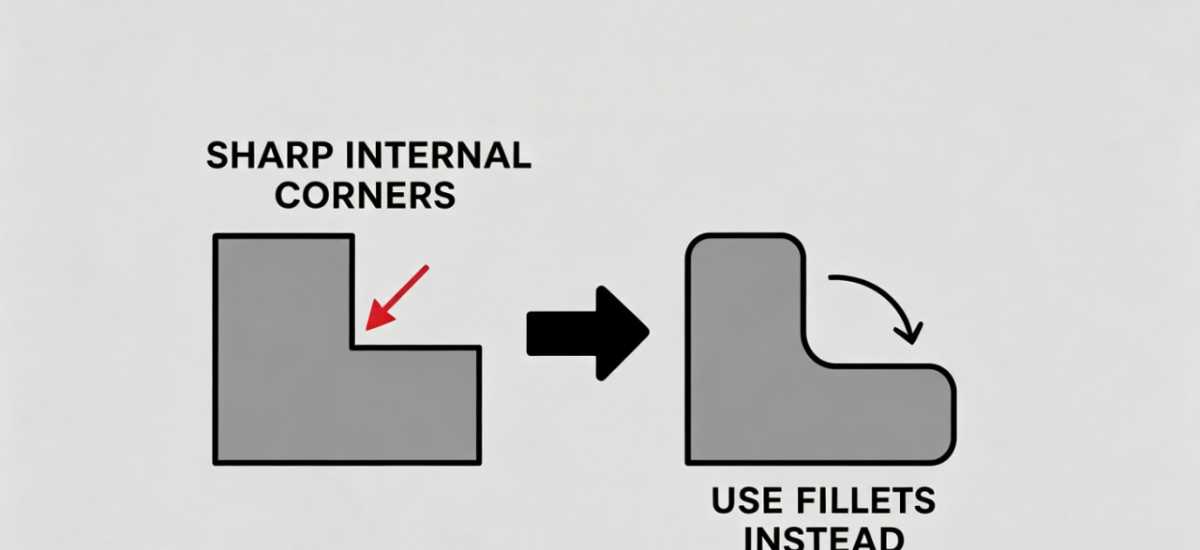
CNC milling uses rotating cutting tools, so internal corners naturally have a radius. When a design specifies a very small internal fillet, the manufacturer may need to use a smaller cutter to reach the corner.
Smaller or long-reach tools have lower rigidity and may require more conservative cutting conditions, especially in deep pockets. Using several different small radii on the same part can also increase tool changes and programming time without adding functional value.
If a truly square internal corner is required for a mating component, machining may need an alternative feature such as a corner relief or a different manufacturing process.
DFM Optimization Tip: Use practical and consistent internal radii wherever the function allows. Avoid very small fillets unless they are necessary, and consider corner relief where a mating part must fit into a nominally square internal corner.
3. Designing Deep, Narrow Pockets and Tall Walls
Deep pockets, narrow slots, and tall internal walls can all create tool-access and rigidity problems during CNC milling. Reaching the bottom of these features often requires a cutter with greater overhang, which reduces tool stiffness and increases the risk of vibration, deflection, and inconsistent surface finish.
As the feature becomes deeper relative to its opening, chip evacuation and coolant access can also become more difficult. Trapped chips may be recut or dragged across finished surfaces, while limited tool access may require additional machining passes or more conservative cutting conditions.
Tall walls create a similar challenge from the workpiece side. Thin or unsupported walls may deflect under cutting forces, especially when the tool must reach deep into the cavity. This can make dimensional control more difficult even when the tool itself is sufficiently rigid.
DFM Optimization Tip: Where the function allows, reduce unnecessary cavity depth, increase pocket or slot width, use practical internal radii, and avoid excessively tall unsupported walls. The goal is to give the cutter enough access and rigidity while maintaining effective chip evacuation.
4. Designing Very Small or Excessively Deep Holes
Very small holes and deep blind holes can become difficult to machine because the cutting tool has limited rigidity and chip evacuation becomes more challenging as hole depth increases.
Small-diameter drills are more sensitive to runout, deflection, and tool breakage. Deep holes create additional problems because chips and coolant must travel farther through a confined space, which can affect hole straightness, surface condition, and process stability.
As the depth-to-diameter ratio increases, the manufacturer may need a different drilling strategy, longer tooling, additional chip-clearing cycles, or specialized deep-hole equipment. These requirements can increase cycle time and process complexity.
DFM Optimization Tip: Use practical hole diameters and depths wherever the function allows. Avoid unnecessarily high depth-to-diameter ratios, and make sure blind holes provide enough depth for the required functional feature without adding extra machining that does not serve the assembly.
5. Designing Thin Walls and Slender Ribs
İnce duvarlar and slender ribs have low stiffness, which makes them more sensitive to cutting forces and clamping pressure during CNC işleme. The feature may deflect while it is being cut and then move again after the tool or fixture load is removed.
This can affect wall thickness, flatness, position, and surface finish. The risk increases when the wall is both thin and tall, has a long unsupported span, or must hold a tight geometric tolerance.
Machining these features may require lighter tool engagement, staged roughing and finishing, additional support, or a more carefully planned toolpath and workholding strategy. These measures can increase machining time even when the final geometry is achievable.
DFM Optimization Tip: Where the function allows, increase wall or rib thickness, reduce unsupported height or length, or add supporting geometry. Define wall thickness together with the material, feature size, and required tolerance rather than applying one minimum value to every CNC part.
6. Adding Complex or Hard-to-Reach Features Without Functional Need
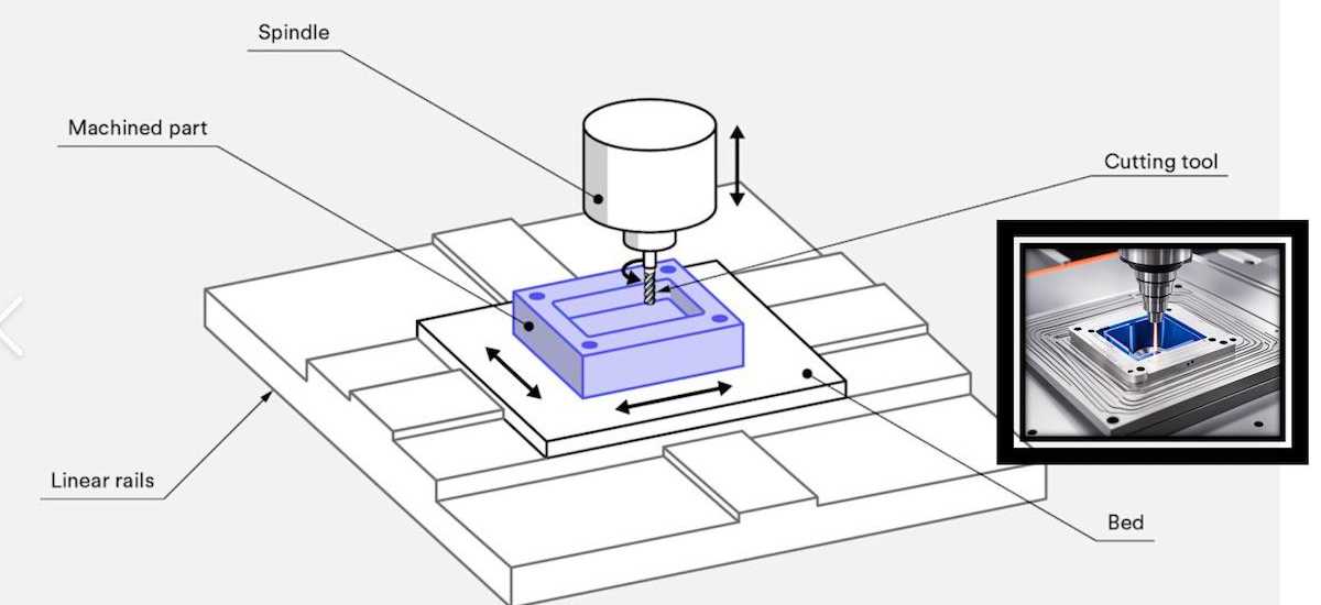
Complex geometry is not a problem when it serves a clear functional purpose. The manufacturing issue appears when a part includes undercuts, deep recesses, sculpted surfaces, side features, or other difficult-to-access geometry that adds machining work without improving fit, strength, or performance.
These features may require longer toolpaths, additional tool changes, multi-axis positioning, special cutters, or extra setups to reach surfaces that cannot be machined from the primary orientation. The added complexity can increase programming time and machining effort even when the feature itself is dimensionally simple.
Features that require access from several directions can also increase setup and inspection requirements, particularly when their position must be controlled relative to other critical geometry.
DFM Optimization Tip: Keep complex geometry where it supports the part’s function, but simplify decorative or non-functional features where possible. Review undercuts, side features, and difficult-to-reach surfaces early to determine whether they justify the additional tooling, axis movement, or setup they require.
7. Over-Specifying Surface Roughness Requirements
Surface roughness should be specified where it affects function, fit, sealing, friction, wear, or appearance. Problems arise when a very low Ra value is applied to the entire part even though only a few surfaces actually require that finish.
Tighter surface-finish requirements may require dedicated finishing passes, different tooling, more controlled cutting conditions, additional inspection, or secondary processes such as polishing or grinding. These extra steps can increase machining time without adding value to non-functional surfaces.
A low Ra value also does not automatically define every aspect of surface quality. Scratches, tool marks, lay direction, or local defects may still matter depending on how the surface is used.
DFM Optimization Tip: Apply tighter surface-finish requirements only to function-critical or cosmetic surfaces. Use practical general finish requirements elsewhere, and specify additional surface characteristics only when the application actually depends on them.
8. Leaving No Practical Surfaces for Workholding and Location
Some parts are difficult to machine not because of the cutting geometry itself, but because there is no stable way to locate and hold them. Thin profiles, irregular outlines, protruding features, or fully functional outer surfaces can leave very little area for reliable workholding.
When suitable locating or clamping surfaces are unavailable, the manufacturer may need custom fixtures, soft jaws, auxiliary supports, or additional setups. Each repositioning step can add setup time and introduce another opportunity for alignment error between machined features.
Workholding also affects tool access. A surface that looks convenient for clamping may block another feature that must be machined in the same setup, forcing the part to be repositioned.
DFM Optimization Tip: Where the design allows, provide stable and accessible surfaces that can be used for locating, supporting, or clamping the part without interfering with critical machining features. Consider how the part can be held through each major machining setup rather than relying on one universal fixture arrangement.
9. Using Ambiguous Dimensions or Datum References
A drawing can contain all the required dimensions and still be difficult to manufacture if those dimensions do not clearly communicate how the part should be located and inspected. Conflicting tolerances, unclear datum references, or dimensions taken from unrelated surfaces can lead to different interpretations during machining and inspection.
Datum features should reflect the functional relationship of the part wherever possible. Surfaces or features used to locate the component in assembly, control mating geometry, or establish critical feature positions are usually more meaningful than arbitrary reference surfaces chosen only for convenience.
Dimensions and GD&T requirements should also follow a consistent reference structure. When the same feature is controlled from several unrelated origins, tolerance relationships become harder to understand and inspect.
DFM Optimization Tip: Choose datum features based on function, assembly, and inspection needs, then dimension critical geometry from that reference system. Avoid duplicate or conflicting requirements, and make sure the drawing communicates the intended relationship between features clearly.
Çözüm
A CNC part does not need to be geometrically simple, but its functional requirements should be practical to machine, locate, inspect, and assemble. Tight tolerances, deep features, thin walls, difficult tool access, and unclear datum structures can all add manufacturing complexity when they are not required by the part’s function.
DFM review is most useful when it identifies these issues before machining begins, while small changes to geometry, tolerances, or feature access are still easy to make.
For custom CNC parts, Beska can review drawings and 3D models for machining access, tolerance requirements, workholding, and other manufacturability concerns before production.
 Turkish
 English
 Hebrew
 French
 Russian
 German
 Spanish
 Portuguese