


Surface finish symbols define how a surface should be produced, measured, and accepted on an engineering drawing. A small change in the symbol or its annotation can affect whether material removal is required, which roughness parameter applies, or whether lay direction and other surface texture requirements must be controlled.
Correct interpretation is especially important for machined surfaces where roughness, sealing, wear, or fit affects part function. This article explains the main surface texture symbols, how to read their callouts under current ISO conventions, how parameters such as Ra and Rz differ, and which drawing mistakes commonly lead to manufacturing or inspection issues.
1. What Do Surface Finish Symbols Mean?
Surface texture symbols indicate whether material removal is required, prohibited, or left unspecified when producing a surface. The basic symbol can be modified with a bar or circle to change that requirement.
Basic Symbol: Material Removal Not Specified
The basic surface texture symbol indicates that the surface must meet the stated texture requirement, but it does not specify whether material has to be removed to achieve it.
The actual manufacturing method therefore depends on the drawing requirement, material, and production process.
Symbol with a Bar: Material Removal Required
Adding a bar to the basic symbol means the specified surface must be produced by removing material.
The removal method is not limited to one process. Depending on the requirement, it may involve machining, grinding, polishing, or another suitable material-removal operation.
Symbol with a Circle: Material Removal Not Permitted
Adding a circle to the basic symbol means the specified surface must be produced without material removal.
This is commonly relevant to surfaces that are intended to remain as cast, forged, molded, or otherwise produced without subsequent cutting or grinding. Any additional treatment still needs to comply with the drawing and the applicable surface specification.
The symbol form should therefore be checked before interpreting roughness values or selecting the manufacturing process.
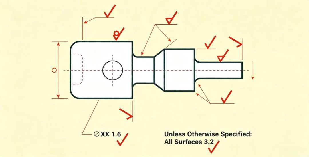
2. How to Read a Surface Texture Callout
A surface texture callout can contain more than a roughness number. Depending on the drawing, it may also specify the roughness parameter, manufacturing method, lay direction, machining allowance, or other requirements that affect how the surface is produced and inspected.
Roughness Parameter and Value
The first item to check is the specified surface texture parameter and its value. Ra is commonly used, but other parameters such as Rz, Rt, or material-ratio parameters may be specified when the surface function requires more information than average roughness alone.
The value should always be interpreted together with the referenced drawing standard and units rather than assumed from the number itself.
Manufacturing Method or Process Requirement
A callout may include a required manufacturing method or treatment, such as grinding, honing, lapping, or another defined process.
When a process is explicitly stated, meeting the roughness value alone may not be enough. The specified method can be part of the functional or inspection requirement.
Lay Direction
Lay indicates the predominant direction of the surface pattern. It becomes important when the orientation of the surface texture can affect sealing, friction, wear, or contact behavior.
If a lay symbol is included, it should be treated as a separate requirement rather than inferred from the manufacturing process.
Machining Allowance and Additional Requirements
For cast, forged, or otherwise near-net-shape parts, the callout may also include a machining allowance or additional surface requirements.
These details should be reviewed together with the part geometry and process plan because they affect how much stock must remain before final machining and how the finished surface will be verified.
Before production, the complete callout should be read as one specification rather than focusing only on the roughness value.
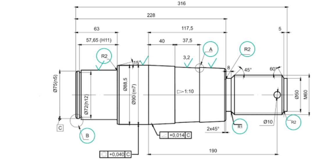
3. Ra, Rz, Rt, and Other Surface Texture Parameters
A surface roughness value is only meaningful when the parameter is clearly defined. Different parameters describe different aspects of the measured profile, so two surfaces with a similar Ra value can still have very different peak, valley, or bearing characteristics.
Ra: Average Roughness
Ra describes the arithmetic mean of the absolute height deviations of the roughness profile. It gives a useful overall indication of surface texture and is widely used on engineering drawings.
Because Ra is an average value, it does not show how individual peaks and valleys are distributed. Surfaces with similar Ra values can therefore still have different profile shapes.
Rz: Profile Height Variation
Rz provides information about the vertical height variation of the roughness profile and is more sensitive than Ra to pronounced peaks and valleys.
Its exact definition depends on the governing standard, so Rz values should always be interpreted together with the referenced surface-texture standard.
Rt: Total Profile Height
Rt represents the total height between the highest peak and the deepest valley within the evaluation length. It therefore highlights the most extreme vertical features present in the measured profile.
Rmr: Material Ratio
Rmr describes the proportion of the profile material present at a specified level. Unlike Ra, Rz, or Rt, it provides information about how much of the surface would support contact at a given profile height.
No single parameter fully describes surface function. The appropriate parameter depends on which aspect of the surface profile needs to be controlled and verified.
4. How Lay Direction Affects Surface Function
Surface lay describes the predominant direction of the surface pattern left by manufacturing or finishing. It is a directional characteristic of the finished surface and should not be interpreted simply as a label for a specific machining process.
Lay direction becomes important when surface orientation affects how two surfaces interact. On sealing interfaces, directional grooves can influence potential leakage paths. On sliding or contacting surfaces, lay orientation can affect friction, lubricant retention, and wear behavior. For coated or bonded surfaces, surface direction may also influence how consistently the interface performs.
When a lay requirement is specified on a drawing, it should be treated as an independent surface condition rather than assumed from the manufacturing method. The same machining process can produce different lay patterns depending on tool path, feed direction, part geometry, and finishing strategy.
For noncritical surfaces, lay may not need to be controlled separately. For functional surfaces, however, the specified lay should be reviewed together with roughness parameters and the intended surface function.
5. ISO 21920 and ASME Surface Texture Conventions
ISO and ASME drawings use similar surface texture symbols, but the governing standards and annotation conventions are not identical. Surface finish requirements should therefore be interpreted from the standard referenced on the drawing rather than from symbol appearance alone.
Current ISO Standard
ISO 21920-1:2021 defines how profile surface texture requirements are indicated in technical product documentation. It replaced ISO 1302:2002, which may still appear on older drawings.
When reviewing an ISO drawing, the parameter designation, numerical value, units, and any additional process or lay requirements should be read together with the referenced standard.
ASME Surface Texture Conventions
ASME Y14.36 defines the symbols used to designate surface texture requirements on engineering drawings. Surface texture terminology and parameter definitions are addressed separately in ASME B46.1.
ASME drawings may use inch or metric units depending on the drawing system, so the unit should not be inferred from the numerical value alone.
What to Check Before Manufacturing
For drawings received from different customers or regions, confirm the referenced standard, measurement units, specified roughness parameter, and any additional notes before production.
A number such as “32” or “3.2” should never be interpreted in isolation. Its meaning depends on the drawing standard, units, and parameter definition.
6. Common Surface Finish Callout Mistakes
Surface finish callouts often create problems not because the symbol is difficult to read, but because the requirement is incomplete, inconsistent, or more restrictive than the part function actually needs.
Over-Specifying Surface Roughness
Specifying a tighter surface requirement than the function requires can add unnecessary finishing operations, inspection effort, and machining time.
Surface roughness should be selected from the functional requirement of the feature rather than from a general preference for a smoother surface.
Mixing Different Drawing Conventions
Using ISO and ASME notation conventions on the same drawing without clearly defining the governing standard can create different interpretations during manufacturing and inspection.
The referenced standard, units, and parameter designation should be consistent throughout the drawing.
Leaving Functional Lay Requirements Undefined
Lay does not need to be specified on every surface, but it can matter when surface direction affects sealing, sliding contact, lubrication, or another functional interface.
If lay is functionally important, it should be defined explicitly rather than assumed from the machining process.
Using Ra as the Only Surface Requirement
Ra describes average roughness but does not fully describe individual peaks, valleys, or material distribution.
Where surface function depends on characteristics that Ra does not capture, additional texture parameters may be needed.
Conflicting Process and Surface Requirements
A drawing can become difficult or impossible to interpret when the required surface texture conflicts with the specified material-removal condition, manufacturing method, or secondary treatment.
These conflicts should be resolved during drawing review rather than left for the machine shop or inspection team to interpret during production.
A good surface finish callout should define only what is functionally necessary and give manufacturing and inspection teams one consistent basis for interpretation.
7. How to Review Surface Finish Requirements Before Machining
Surface finish requirements should be reviewed together with the feature function, material, machining process, and inspection method before production begins.
The first check is whether the callout is complete and consistent. The referenced standard, roughness parameter, numerical value, units, lay requirement, and any specified manufacturing method should describe the same surface condition without conflicting instructions.
The requirement should also be compared with the intended manufacturing process. A surface texture that is technically achievable may still require additional finishing operations, different tooling, or a change in process sequence. Where the requirement affects sealing, sliding contact, fit, or another functional interface, the inspection method should be confirmed at the same time.
Ambiguous or conflicting callouts are best resolved before CNC programming and machining begin. Beska reviews surface texture requirements together with other drawing specifications during manufacturing review so that unclear or unnecessarily restrictive requirements can be identified before production.
Çözüm
Surface finish symbols are only useful when the complete requirement is interpreted correctly. The governing standard, surface texture parameter, material-removal condition, lay direction, and any process-specific notes should be read together rather than treated as separate annotations.
For current ISO drawings, ISO 21920 provides the relevant framework for surface texture indications, while older drawings may still reference ISO 1302. In either case, unclear or conflicting callouts should be resolved before machining and inspection begin.
At Beska, surface texture requirements are reviewed together with tolerances, material specifications, and other drawing details during CNC manufacturing review. This helps identify ambiguous or unnecessarily restrictive requirements before they affect tooling, machining, or inspection.
 Turkish
 English
 Hebrew
 French
 Russian
 German
 Spanish
 Portuguese