


Burrs are a common result of CNC cutting when material near an edge deforms instead of separating cleanly. Depending on where they form, even small burrs can interfere with mating surfaces, affect inspection, create sharp handling edges, or add an extra çapak alma step before the part is ready for assembly.
Their size and shape are not controlled by one parameter alone. Workpiece material, tool geometry and condition, cutting parameters, and the way the cutting edge enters or leaves the part can all change how a burr forms.
The key questions are how these burrs develop, which machining conditions make them more severe, and how tool selection, toolpath, and process control can reduce them before a separate deburring operation is needed.
1. What is a Burr in CNC Machining?
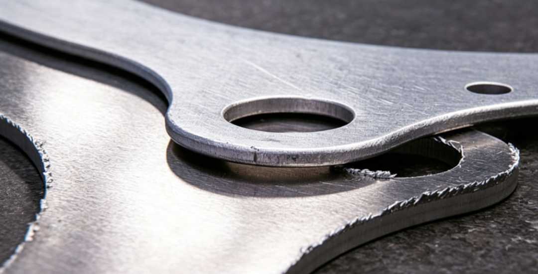
A burr is unwanted material that remains at or extends beyond the intended edge of a machined part. It forms when material near the cutting edge does not separate completely during the cutting process.
Burrs are often described according to where or how they form. An entry burr may appear where the tool enters the workpiece, while an exit burr forms near the point where the cutting edge leaves the material. Terms such as top burr, bottom burr, and roll-over burr are also used in milling and other cutting operations to describe different edge conditions.
Most burr formation involves plastic deformation near the edge. Instead of being removed cleanly as a chip, some material may bend, stretch, or roll over before it separates. Material properties influence this behavior: more ductile materials can sustain greater deformation before fracture, while more brittle materials tend to fail differently at the edge.
The final burr shape and size therefore depend not only on the material, but also on the cutting process, tool geometry, tool condition, and how the cutting edge enters or exits the workpiece.
2. Why Burrs Matter for Machined Parts
Burrs are more than a cosmetic edge defect. Depending on their location and size, they can affect assembly, inspection, handling, and downstream finishing.
Assembly and Fit
A burr on a mating or locating surface can prevent parts from seating correctly or shift their relative position during assembly. This becomes more important when several components rely on the same reference surfaces or locating features.
Automated assembly can also be sensitive to burrs because insertion, gripping, and positioning depend on consistent edge geometry. An unexpected burr may increase resistance, disturb alignment, or interrupt the assembly sequence.
Measurement and Inspection
Burrs can interfere with dimensional inspection when a probe, gauge, or fixture contacts the burr instead of the intended part surface. This can produce a measurement that does not represent the true machined geometry.
Critical inspection surfaces should therefore be free of interfering burrs before final dimensional verification.
Safety and Downstream Finishing
Sharp burrs create handling risks and may require additional edge finishing before parts can be safely assembled or packaged.
They can also affect surface preparation and finishing. Irregular edges may influence coating coverage, plating appearance, or the final edge condition, particularly when the drawing requires a controlled chamfer, radius, or edge break.
3. Factors That Influence Burr Formation
Burr formation is influenced by the interaction between the workpiece material, cutting tool, machining parameters, and the way the cutting edge enters and leaves the workpiece. Changing one variable can alter the burr, but its effect cannot always be separated from the others.
Material Properties and Condition
Ductility, hardness, strength, microstructure, and heat-treatment condition all influence how material behaves near a machined edge. More ductile materials can undergo greater plastic deformation before separation, while more brittle materials may fracture or break away differently at the edge.
This does not mean that one material always produces larger burrs than another. Different aluminum alloys, stainless steels, titanium grades, or material tempers can respond differently under the same nominal cutting conditions.
Material variation between batches can also change machining behavior, but it should be considered alongside tool condition, cutting parameters, and machine setup rather than assumed to be the cause of a burr change.
Tool Geometry and Edge Condition
Rake angle, cutting-edge radius, edge preparation, tool coating, and tool wear affect chip formation and the forces acting near the workpiece edge.
A sharp cutting edge generally promotes cleaner shearing, while a worn or unsuitable edge can increase ploughing and plastic deformation. However, the tool geometry should be selected for the specific material and machining operation rather than using one rake-angle rule for all applications.
Kesme Parametreleri
Cutting speed, feed per tooth, and depth of cut can all change burr formation, but their effects are strongly linked to material, tool geometry, and the type of burr being evaluated.
For this reason, simple rules such as “lower feed produces smaller burrs” or “higher speed reduces burrs” are not reliable across all CNC operations. Parameters should be optimized as a combination and verified on the actual material and feature.
Toolpath and Edge Exit Conditions
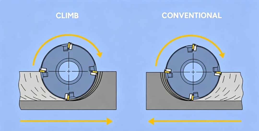
The way the cutting edge leaves the workpiece is especially important in milling. Workpiece support near the exit edge, cutter engagement, exit angle, and toolpath direction can all change where a burr forms and how large it becomes.
Climb and conventional milling therefore do not produce one universal burr pattern. A more useful strategy is to plan the toolpath so that critical edges have favorable support and, where possible, the tool exits toward an edge where burr formation is easier to control or remove.
4. How to Reduce Burr Formation During CNC Machining
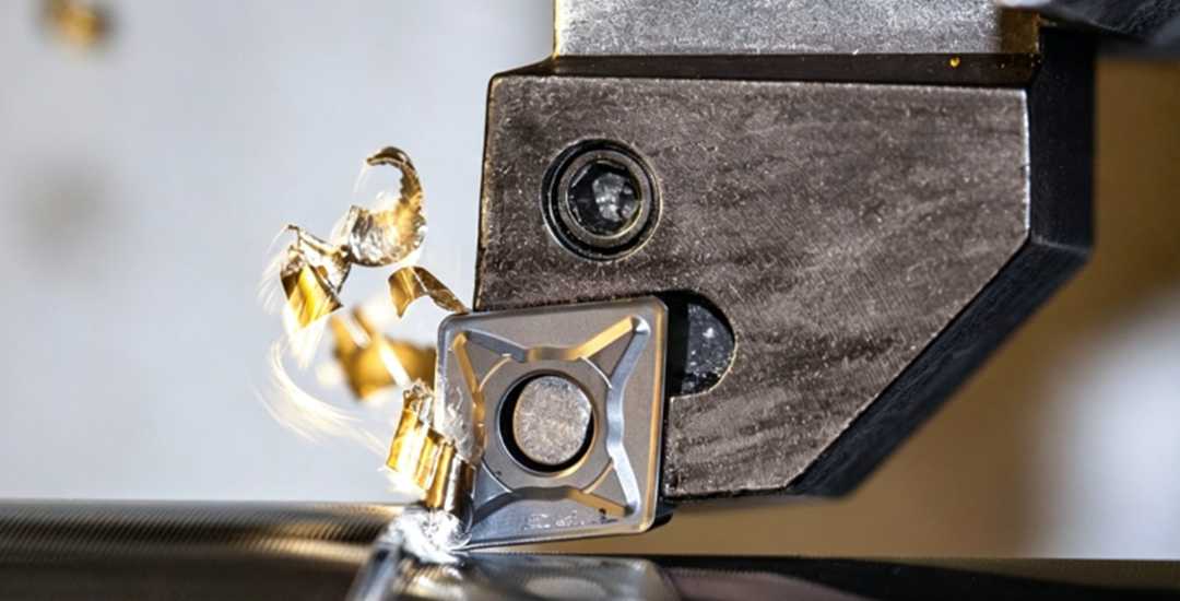
Reducing burrs starts with controlling the cutting process rather than relying on deburring afterward. Tool condition, cutting parameters, and the way the tool approaches critical edges should be considered together.
Optimize Cutting Parameters as a System
Cutting speed, feed, and depth of cut all influence chip formation and plastic deformation near the workpiece edge. Their effects, however, depend on the material, cutter geometry, machining operation, and type of burr being formed.
For this reason, changing one parameter in isolation is not a reliable burr-control strategy. Finishing conditions should be established for the actual material and feature, with particular attention to chip formation and the condition of the edge where the tool leaves the workpiece.
Very light cuts are not automatically better. If the undeformed chip thickness becomes too small relative to the cutting-edge radius, the tool may plough or deform the material instead of shearing it efficiently.
Monitor Tool Condition
A sharp and suitable cutting edge generally produces more controlled chip formation than a worn or damaged tool. As the cutting edge changes through flank wear, adhesion, chipping, or built-up edge, burr size and shape may also change.
An increase in burr size during an otherwise stable production run can therefore be a useful sign to inspect the tool. However, there is no universal flank-wear value at which burrs suddenly become unacceptable. Tool-change limits should be established for the actual cutter, material, machining conditions, and edge requirements.
Tool life can be managed using part count, cutting time, inspection results, or condition monitoring depending on the stability of the process.
Control the Tool Exit
Burrs frequently develop where the cutting edge leaves an unsupported workpiece edge. Toolpath planning can therefore be used to change the exit location, exit angle, or amount of material supporting the edge during cutting.
Where geometry allows, the tool can be directed away from critical mating or locating edges, or the machining sequence can be adjusted so that the edge remains supported for longer. The preferred strategy should be verified on the actual part rather than assuming that one milling direction always produces the smallest burr.
5. Common Burr Problems and Troubleshooting
Burr patterns can provide useful clues about what is happening in the cutting process, but one observation rarely points to a single cause. Tool condition, material behavior, cutting parameters, and edge-exit conditions should be checked together.
| Observation | What to Check First |
| Burrs gradually increase during a production run | Cutting-edge wear, built-up edge, tool damage, and chip evacuation |
| Burrs are concentrated on one edge | Tool exit location, exit angle, workpiece support, and toolpath direction |
| Burr behavior changes after a tool replacement | Tool geometry, edge preparation, coating, runout, and cutting parameters |
| Burrs change after a new material batch | Material hardness, temper, microstructure, and interaction with the existing cutting conditions |
| Deburring changes critical dimensions | Deburring method, edge-removal amount, and drawing-defined edge requirement |
A sudden change in burr size should therefore be treated as a process signal rather than automatically attributed to tool wear. Comparing the affected parts with earlier production, tool condition, and recent changes to the setup usually gives a clearer starting point for troubleshooting.
6. How to Specify Burr and Edge Requirements on a Drawing
A general note such as “remove all burrs” may be sufficient for non-critical edges, but functional edges often need a clearer requirement. Mating surfaces, sealing edges, locating features, electrical contacts, and handling edges may each require a different finished condition.
If a specific chamfer or radius is functionally required, it should be dimensioned directly on the drawing. This gives the manufacturer a defined geometry to machine and inspect rather than leaving the amount of edge removal open to interpretation.
For edges where the exact shape is not defined, ISO 13715 provides a standardized way to indicate permitted material removal or excess material at an edge. This can be useful when the designer needs to control burr direction or edge condition without specifying a full chamfer or radius.
Critical edge requirements should also consider the inspection method. A requirement that cannot be measured consistently may lead to different interpretations between the manufacturer and customer, so the drawing should distinguish between general deburring and function-critical edge control.
Çözüm
Burr formation cannot be controlled by one cutting parameter alone. Material behavior, tool condition, cutting geometry, and the way the tool enters or leaves an edge all influence the final result.
Good burr control therefore starts during process planning, not only after machining is complete. Critical edges should be considered together with toolpath, cutting conditions, and the drawing requirement so that any remaining burr can be removed without changing the intended geometry.
For CNC machined parts, Beska can combine machining, controlled edge finishing, and dimensional inspection according to the functional requirements of the drawing, especially where mating, locating, sealing, or handling edges need consistent control.
 Turkish
 English
 Hebrew
 French
 Russian
 German
 Spanish
 Portuguese