


A chamfer is a flat angled surface machined along an edge or corner. On CNC parts, it may be used to remove a sharp edge, provide an assembly lead-in, prepare an edge for another operation, or create a defined visual feature.
Although the geometry is simple, the required angle, size, tolerance, machining method, and inspection approach depend on what the chamfer needs to do. A feature that works as a general edge break may not be suitable for a controlled mating or assembly surface.
This article explains how CNC chamfers are defined on drawings, how they are machined and inspected, and which design and process factors affect consistent results.
1. What Is CNC Chamfering?
CNC chamfering is the machining of a flat, angled surface along an edge or corner of a part. A 45° chamfer is common, but other angles can be used when required by the design.
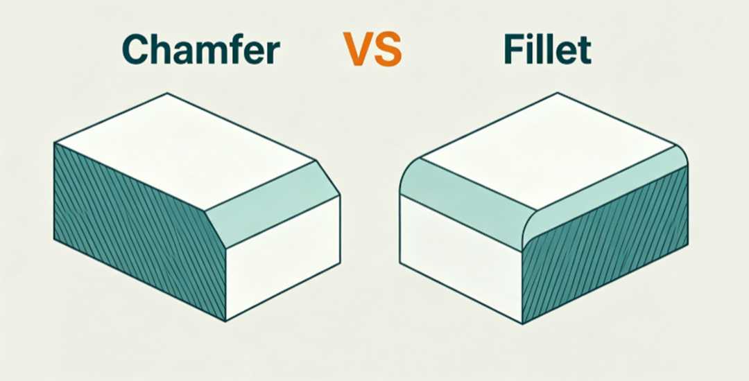
Chamfers are often added to remove sharp edges, provide a lead-in during assembly, prepare the entrance to a hole or thread, or create a defined edge appearance. The required geometry depends on the function of the feature rather than on a single standard chamfer size.
Chamfer vs Edge Break vs Fillet vs Countersink
These features are related, but they are not interchangeable.
| Özellik | Geometry | Typical Purpose |
| Chamfer | Flat angled surface | Assembly lead-in, defined edge geometry, edge preparation |
| Edge Break | Small removal of a sharp edge; geometry may be less tightly defined | Safe handling, burr removal |
| Fillet / Radius | Rounded transition | Smooth geometry transition, stress-sensitive areas |
| Countersink | Conical feature around a hole | Seating a countersunk fastener or creating a controlled hole entrance |
A chamfer therefore refers to a defined flat bevel, while an edge break describes the condition required at an edge. A fillet uses a curved profile instead of a flat surface, and a countersink is a hole-related feature with its own angle and diameter requirements.
2. Why Chamfers Are Used on CNC Parts
Chamfers are added to CNC parts for different functional reasons. Their size, angle, and tolerance should reflect what the edge needs to do in the finished part.
Assembly Lead-In
A chamfer can help guide one component into another during assembly. Common examples include shafts entering bores, pins entering locating holes, and mating parts that need a smoother initial engagement.
The chamfer reduces the chance of the edges catching during insertion, but its geometry should be matched to the mating clearance and assembly direction.
Edge Safety and Handling
Machined edges may remain sharp even after the main cutting operation is complete. A small chamfer can remove the sharp corner and make the part safer to handle during inspection, assembly, packaging, and use.
When the purpose is simply to remove a sharp edge rather than create a controlled geometry, an edge-break requirement may be more appropriate than a tightly dimensioned chamfer.
Thread and Hole Entry
Chamfers are commonly added around holes and threaded features to provide a cleaner entrance and reduce interference at the edge.
On threaded holes, the entry chamfer can help with thread starting and remove the sharp edge left at the opening. The required geometry should still be distinguished from a countersink, which is a separate conical feature with its own dimensional requirements.
Functional Edge Preparation
Some parts need a controlled edge before heat treatment, coating, sealing, or another manufacturing operation. In these cases, a chamfer may help remove a severe sharp corner or provide a more suitable transition.
Its benefit depends on the material and downstream process, so chamfering should not be treated as a universal requirement for heat-treated, coated, or sealed parts.
Appearance
Chamfers can also be used as a visible design feature. A consistent bevel can make an exposed edge look more deliberate and finished, especially on machined housings, panels, knobs, and other visible components.
For cosmetic chamfers, consistency across adjacent edges is often more important than applying an unnecessarily tight dimensional tolerance.
3. How to Specify a Chamfer on an Engineering Drawing
A chamfer should be defined clearly enough that its size and angle can be machined and inspected without relying on interpretation. The appropriate callout depends on the chamfer geometry and the drawing standard being used.
Chamfer Size and Angle
A defined chamfer is commonly specified by a linear dimension and an angle. For example:
0.5 × 45° describes a 45° chamfer with a 0.5 mm leg measured from the original corner along the adjoining surface. The value does not refer to the length of the sloped chamfer face.
When the chamfer angle is not 45°, both the required linear dimension and angle should be shown clearly rather than assuming a standard geometry.
What Does C0.5 Mean?
The notation C0.5 is commonly seen on JIS-based and many Asian engineering drawings. It indicates a 0.5 mm chamfer at 45°.
This notation should not be treated as a universal drawing convention. On drawings following other standards, the same feature may instead be shown as 0.5 × 45°. The drawing standard and general notes should therefore be checked before interpreting abbreviated chamfer callouts.
Chamfer Tolerances
Not every chamfer requires a tight dimensional tolerance. An edge used only to remove sharpness may need much less control than a chamfer that locates a mating component or affects assembly.
Tolerance should therefore be assigned according to the function of the feature and the inspection method available. Applying unnecessarily tight tolerances to non-critical chamfers can increase machining and inspection effort without improving part performance.
Chamfer vs Countersink Callouts
A chamfer at the entrance of a hole should not automatically be treated as a countersink.
A chamfer defines an angled edge around the hole, while a countersink is a controlled conical feature usually specified by its major diameter and included angle, or by depth and included angle. When the feature is intended to seat a countersunk fastener, the drawing should define it as a countersink rather than relying on a general chamfer note.
Defined Chamfers and Undefined Edges
ISO 13715 applies to edges where the exact final edge shape is not geometrically defined, such as requirements controlling burrs, undercuts, or general edge conditions.
When a specific chamfer geometry is required, such as 1 × 45°, the feature should instead be dimensioned as a defined geometry using the general dimensioning principles of ISO 129-1.
This distinction is important: an instruction to “break sharp edges” does not define the same manufacturing requirement as a dimensioned chamfer.
4. CNC Chamfering Methods and Tool Selection
CNC chamfers can be produced with different tools and machining strategies. The most suitable method depends on the chamfer angle, edge geometry, tool access, part material, and whether the feature is on a milled, drilled, or turned surface.
Chamfer Mills
Dedicated chamfer mills are commonly used for straight edges, external profiles, hole entrances, and other accessible chamfers with a defined angle.
Because the tool geometry already matches the required bevel, the chamfer can often be produced in a simple contouring pass. The available cutter angle must still match the drawing requirement, and tool size and access need to be considered around pockets, shoulders, and nearby features.
End Milling and Contour Chamfering
A standard end mill or other contouring tool can be used when the chamfer follows a complex path or when the required geometry cannot be produced efficiently with a fixed-angle chamfer mill.
This approach provides more flexibility for irregular or three-dimensional edges, but the final surface depends on toolpath strategy, step-over, cutter geometry, and machine accuracy.
Hole Chamfering and Countersinking
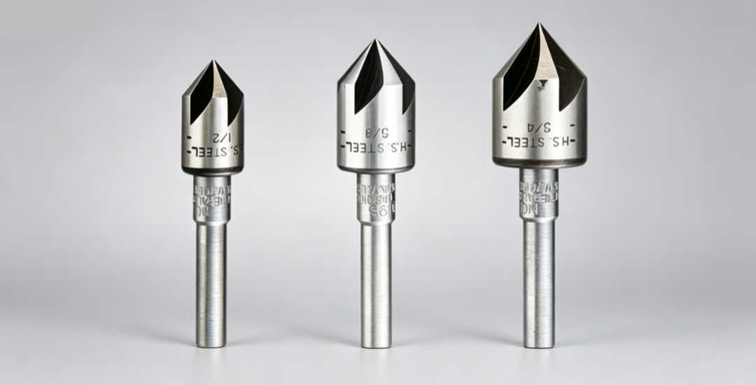
Hole entrances can be chamfered using chamfer tools, spot drills, countersink tools, or other suitable cutters depending on the required feature.
A simple hole-entry chamfer should be distinguished from a countersink intended for a fastener. The tooling should therefore be selected from the actual drawing geometry rather than treating all angled hole features as the same operation.
Chamfering on Turned Parts
On CNC lathes, chamfers can be produced directly with the turning tool or with dedicated tooling during the same setup.
This is common on shaft ends, shoulders, grooves, and threaded features. When possible, machining the chamfer in the same turning setup can reduce additional handling and help maintain its relationship to adjacent diameters and faces.
Form and Special Tooling
Special or form tools may be useful when a repeated edge profile needs to be produced efficiently or when several related features can be machined in one operation.
Their advantage is not simply production volume. The decision also depends on geometry stability, tool access, required consistency, tool cost, and how likely the part design is to change.
5. Design Considerations for CNC Chamfers
A chamfer should be designed around the function of the edge and the geometry available for machining. Even a small bevel can affect wall thickness, nearby features, tool access, or inspection if it is placed in a constrained area.
Match the Chamfer to Its Function
The first question is what the chamfer needs to do. An assembly lead-in, a general edge break, a visible cosmetic bevel, and a controlled mating feature do not require the same geometry or tolerance.
The chamfer should be large enough to perform its intended function without removing more material than necessary from the surrounding feature.
Chamfer Size and Angle
Angle and size should be selected together. Changing either value changes how much material is removed and how the chamfer interacts with adjacent faces.
A larger chamfer may improve lead-in or visibility, but it can also reduce the remaining section around thin walls, small bosses, narrow lands, or features close to an edge. The surrounding geometry should therefore be checked rather than applying a fixed chamfer size across the entire part.
Wall Thickness and Nearby Features
Chamfers near thin walls, holes, slots, shoulders, threads, or sealing features need additional attention because the removed material may affect the remaining geometry.
The risk depends on the local section, load path, feature spacing, and part function. For this reason, wall thickness should not be controlled by a universal chamfer-to-thickness ratio.
Tool Access
A chamfer is only practical if the cutting tool can reach the edge at the required angle without interfering with surrounding geometry.
Deep pockets, internal corners, back-side edges, tall walls, and closely spaced features can limit access or require a different tool, setup, or machining strategy. These constraints are easier to address during DFM than after the toolpath has already been planned.
Tolerance and Inspection
Chamfer tolerances should reflect the importance of the feature. A cosmetic edge or general edge break usually does not need the same level of control as a chamfer that affects assembly or mating geometry.
Measurement should also be considered during design. Small or difficult-to-access chamfers may require optical or other non-contact inspection methods, while larger accessible features may be checked with conventional dimensional equipment.
6. Process Control and Inspection
Chamfer dimensions can change even when the rest of the part remains within tolerance. Tool condition, runout, offset, machine stability, burr formation, and the inspection method can all affect the measured result.
Tool Condition and Runout
Wear or damage at the cutting edge can change the effective chamfer geometry and leave an inconsistent surface. Tool runout can also cause one cutting edge to remove more material than another, particularly on small chamfers where minor variation becomes more noticeable.
For controlled chamfers, tool condition and runout should therefore be checked as part of the machining setup rather than relying only on visual inspection of the finished edge.
Tool Offset and Machining Stability
Chamfer size is sensitive to the programmed tool position. An incorrect radial or axial offset can change the resulting bevel even when the cutter angle is correct.
Machine temperature, workholding, part location, and tool replacement can also shift the process. First-piece inspection is useful for confirming the setup, but critical chamfers should continue to be monitored once the machining process reaches a stable condition.
Burrs and Edge Quality
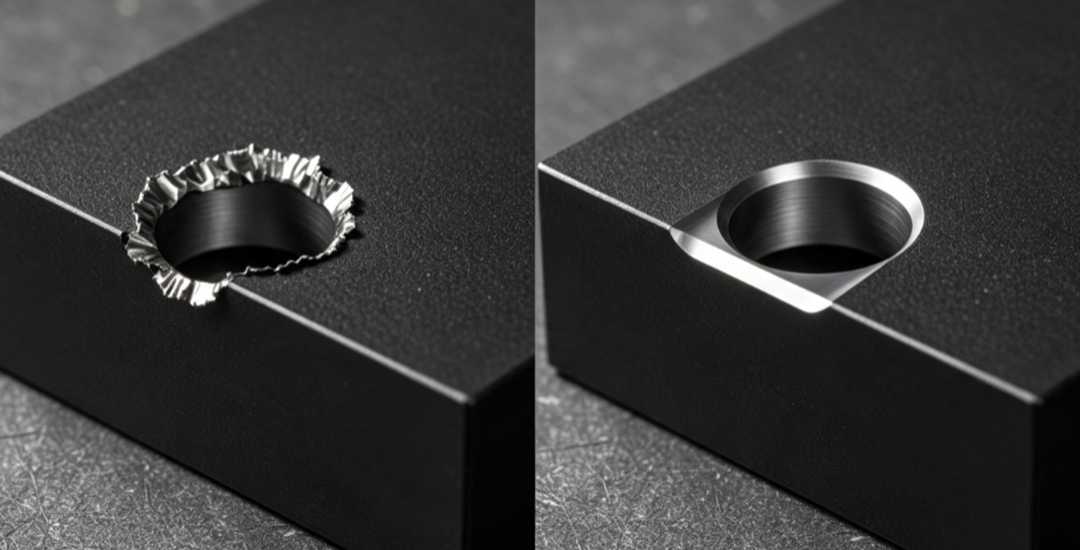
A chamfering operation can still leave burrs, especially where the tool exits the material or intersects another feature. Burrs may affect both the functional edge and the apparent chamfer size during inspection.
Tool condition, cutting direction, engagement, material behavior, and downstream deburring should therefore be considered together when edge quality is important.
Chamfer Measurement
Chamfers can be more difficult to inspect than simple linear dimensions because both the edge location and the angled surface need to be identified consistently.
The appropriate method depends on chamfer size, accessibility, tolerance, and part geometry. Optical or vision systems can be useful for evaluating small profiles, while CMMs, profile measurement systems, dedicated gauges, or other dimensional equipment may be suitable for larger or more accessible features.
For critical chamfers, the inspection method should be defined together with the drawing requirement so that the feature can be measured with sufficient repeatability.
Inspection frequency should also be based on process stability, tolerance, tool-wear behavior, and part risk rather than a fixed number of parts.
7. Common CNC Chamfering Problems
Chamfering problems are often caused by a combination of tool condition, material behavior, workholding, toolpath, and cutting conditions. The visible defect alone does not always identify the root cause.
Inconsistent Chamfer Size
Chamfer size may vary between parts or around the same component when tool offset, runout, wear, part location, or machine stability changes during machining.
If the variation appears gradually, tool wear or thermal drift may be involved. Irregular variation may point instead to runout, workholding, or inconsistent part positioning.
Burrs
Burrs commonly appear where the chamfering tool exits the material or crosses another edge. Their size and direction depend on the material, cutter condition, engagement, and toolpath.
Changing only feed or speed may not solve the problem if the burr is being created by the exit condition or by poor edge support.
Edge Chipping
Chipping can occur when the material is brittle, the cutting edge is damaged, or the chamfering operation places excessive load on the corner.
This is more likely to require a review of tool geometry, engagement, material condition, and cutting strategy rather than a single parameter adjustment.
Thin-Wall Distortion
Thin walls and narrow sections can move under cutting force, causing the chamfer to become uneven or larger than intended.
The problem may come from insufficient support, workholding, tool engagement, or the stiffness of the local geometry. In these cases, the surrounding part structure matters as much as the chamfer itself.
Kötü Yüzey Kaplaması
Visible tool marks, tearing, or an uneven chamfer surface can result from worn tooling, runout, unstable cutting, inappropriate parameters, or limited machine and workpiece rigidity.
For cosmetic or mating chamfers, surface quality should be evaluated together with dimensional accuracy rather than treated as a separate issue.
8. How to Choose the Right Chamfering Approach
The machining method should be selected from the function and geometry of the chamfer first, then checked against tool access, tolerance, inspection requirements, and the available machine setup.
| Design or Production Question | What to Check |
| What does the chamfer need to do? | Edge break, assembly lead-in, thread entry, cosmetic bevel, or controlled mating feature |
| What geometry is required? | Angle, size, straight or contoured edge, internal or external location |
| Can the tool reach the feature? | Pocket depth, surrounding walls, back-side access, nearby geometry |
| How tightly must it be controlled? | Functional tolerance, surface requirement, and inspection capability |
| Which machining method fits the part? | Frezeleme, turning, hole chamfering, contour machining, or special tooling |
| Does production volume affect the method? | Whether the geometry is stable enough to justify dedicated tooling or automation |
A standard chamfer mill may be efficient for an accessible fixed-angle edge, while a complex contour may require a different toolpath or machining strategy. Turned components, hole features, and back-side chamfers may each call for a different approach.
Production volume matters only after the feature has been shown to be manufacturable and inspectable. Dedicated tooling or automation may improve efficiency for repeat production, but they do not replace the need for suitable geometry, access, and process control.
Çözüm
A chamfer may be a small feature, but its geometry can affect assembly, edge condition, appearance, and how easily the part can be machined and inspected. The required size, angle, tolerance, and machining method should therefore be based on the function of the edge rather than on a default chamfer rule.
Clear drawing callouts, suitable tool access, stable machining, and an appropriate inspection method all help keep chamfer dimensions consistent in production.
For custom CNC parts, reviewing chamfer requirements during DFM can identify unnecessary tolerances, access limitations, or inspection challenges before machining begins.
 Turkish
 English
 Hebrew
 French
 Russian
 German
 Spanish
 Portuguese