


A shaft that measures perfectly on the machine can still fail in the assembly. Bearings may not fit properly, seals may leak, or excessive runout may cause vibration during operation. The drawing specifies ±0.01 mm, yet diameter alone does not guarantee reliable performance.
Successful precision shaft machining depends on much more than holding a tight tolerance. Material selection, workholding, machining strategy, and inspection all influence the final result. This article explains the factors that have the greatest impact on shaft quality and highlights the manufacturing challenges that commonly lead to scrap or assembly problems.
1. What Is Precision Shaft Machining
Precision shaft machining is the process of manufacturing shafts with tightly controlled diameters, runout, straightness, and surface finish to ensure reliable performance in rotating and linear motion systems.
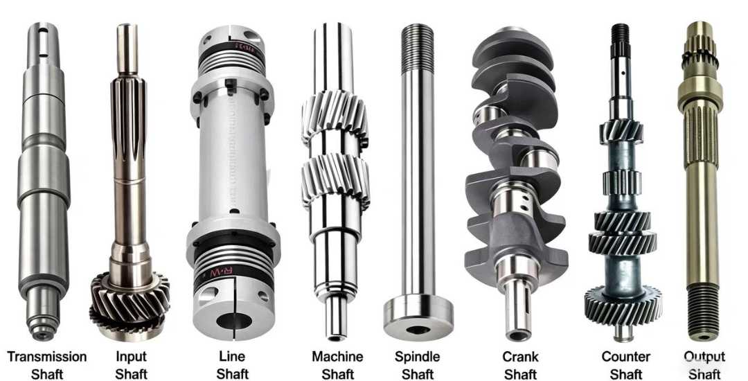
Motor shafts require accurate bearing journals and smooth sealing surfaces. Drive shafts transmit torque through splines or keyways while maintaining straightness under load. Linear shafts guide motion and demand high straightness over their full length. Although their applications differ, they all depend on precise machining of critical features rather than the shaft as a whole.
One of the biggest manufacturing challenges is the length-to-diameter ratio. When the ratio exceeds 8:1, shaft deflection becomes a significant concern during machining. Above 25:1, the shaft is generally considered slender, and maintaining dimensional accuracy often requires tailstock support, steady rests, or between-centers machining.
2. Materials for Shaft Machining
Material selection drives machinability, strength, fatigue life, and cost. The choice comes down to balancing these factors against the application’s demands. The table below summarizes the common options; the sections that follow explain the tradeoffs in more detail.
| Malzeme | Çekme Dayanımı | İşlenebilirlik | Typical Application |
| 1215 Steel | Ilıman | Çok Yüksek | High-volume motor shafts |
| 4140 Alloy | Very High (heat-treated) | Ilıman | Drivetrain, gearboxes |
| 303/304 Stainless | Moderate-High | Daha düşük | Marine, chemical, medical |
| 6061 Alüminyum | Ilıman | Yüksek | Automation, lightweight systems |
| 17-4 PH | Çok Yüksek | Düşük | Aerospace, high-strength |
| Ti-6Al-4V | Çok Yüksek | Poor | Havacılık ve uzay, tıbbi implantlar |
Source: Manufacturer technical data sheets.
4140 Alloy Steel
This is the go-to for heavy torque transmission. Heat-treated to high tensile strength, it handles heavy loads but requires lower cutting speeds. Machinability is moderate; tool wear is predictable. Common in drivetrain and gearbox shafts.
303 and 304 Stainless Steel
These offer corrosion resistance for marine and chemical environments. 303 machines better due to added sulfur for chip breakage. 304 is tougher and work-hardens more readily. Tool life drops compared to carbon steel, and work hardening becomes a concern if feeds aren’t aggressive enough.
6061 Alüminyum
This machines fast and handles lightweight applications. Tensile strength is adequate for many automation and motor applications but insufficient for heavy industrial torque loads. The real advantage is speed: higher cutting speeds, longer tool life, and shorter cycle times.
1215 Free-Machining Steel
This is the choice for high-volume production where strength requirements are moderate. It machines fast with excellent chip control, making it cost-effective for motor shafts and general-purpose components.
17-4 PH and Ti-6Al-4V
These are specialty materials for aerospace and medical applications. They machine poorly, wear tools aggressively, and require rigid setups. Only specify these when the application demands their corrosion resistance or high-temperature strength.
The best material for a shaft is rarely the strongest one on the datasheet. For high-volume production, 1215 steel offers the lowest cost per part. For heavy loads, 4140 is the practical choice. For corrosion resistance, 303 or 304 stainless. For lightweight applications, 6061 aluminum. The wrong material adds cost or creates failure risk. Match it to the load, environment, and production volume, not to the highest number.
3. Tolerances: What’s Realistic and What Requires Grinding
A common design mistake is specifying tighter tolerances than the application actually requires. Tight tolerances increase machining time, inspection effort, and production cost, but they do not always improve shaft performance. Functional surfaces deserve tighter control, while non-critical features usually do not.
Turned Diameters
Modern CNC tornalama provides excellent dimensional accuracy under stable machining conditions with proper tooling and workholding. Most shaft features can be finished by turning alone, including general bearing fits and structural diameters. Pushing turning beyond its practical capability increases sensitivity to tool wear, temperature variation, and material inconsistency.
Hard Turning vs. Grinding
Hard turning with CBN inserts provides high accuracy on hardened components and can reduce or eliminate grinding for some applications. Cylindrical grinding delivers better roundness, straightness, and surface finish, making it the preferred process for bearing journals, seal surfaces, and other critical mating diameters. Grinding should be applied where it improves function, not simply because tighter tolerances are specified.
Runout Matters More Than Diameter Alone
Holding the specified diameter does not guarantee that a shaft will perform properly. Excessive runout can cause vibration, premature bearing wear, and sealing problems even when every diameter is within tolerance. For rotating shafts, runout often has a greater influence on performance than diameter alone.
When Is Grinding Necessary
Bearing seats, seal contact surfaces, and other precision mating features often justify grinding because they require better roundness, lower runout, and finer surface finish. Most non-critical shaft diameters can be produced efficiently by turning without sacrificing performance. Applying grinding to unnecessary features increases cycle time and manufacturing cost while providing little practical benefit.
The machining process should match the function of each feature. Grinding belongs on surfaces where accuracy directly affects performance, while turning remains the most practical and economical choice for the majority of shaft features.
4. Manufacturing Methods and Workholding
Most precision shafts contain multiple diameters, shoulders, bearing seats, sealing surfaces, and threaded features. The machining sequence and workholding method determine whether these features remain aligned throughout production.
Machining Sequence
Rough turning removes material efficiently, while finish turning establishes the final diameters, shoulder locations, and surface finish. Heavy cuts without adequate support can cause shaft deflection, taper, and dimensional variation, particularly on long workpieces.
Workholding
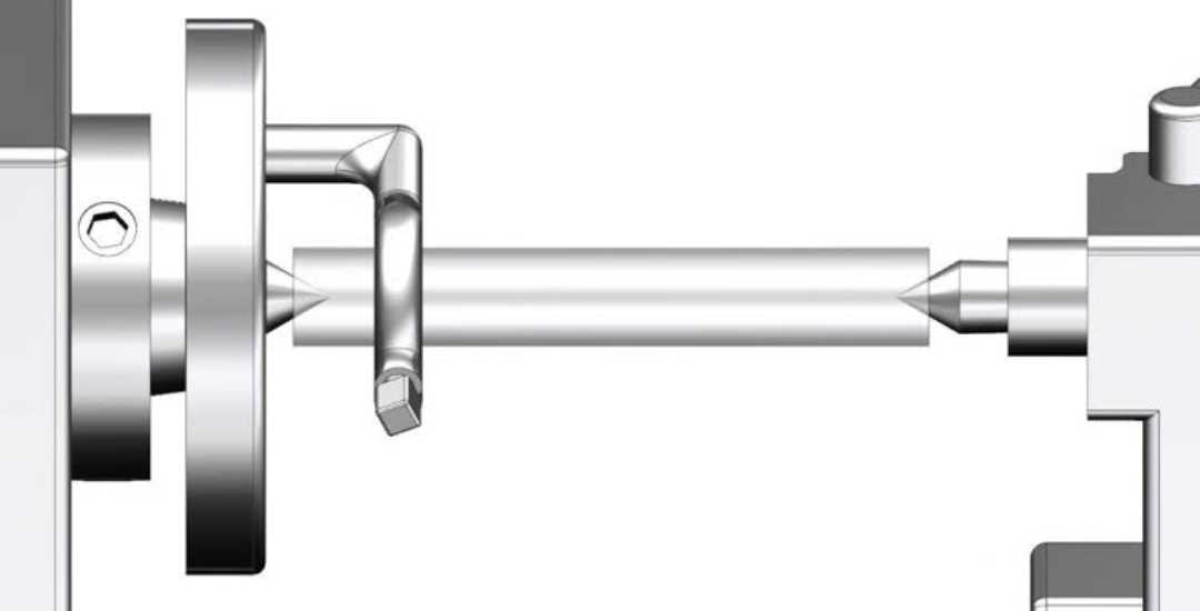
Short shafts are typically machined using a three-jaw chuck or collet. As the length-to-diameter ratio increases, tailstock support becomes necessary to reduce deflection. Long shafts often require steady rests to maintain rigidity throughout machining.
Between-Centers Turning
Between-centers turning provides the highest accuracy for long shafts. The shaft rotates on precision centers rather than relying on chuck alignment, improving concentricity and minimizing runout across all machined diameters. This method is widely used for bearing journals and other high-precision shaft applications.
Workholding Considerations
Center holes should be included whenever between-centers machining is planned. Long shafts benefit from suitable support locations for steady rests, while unnecessary unsupported lengths should be minimized wherever possible.
A stable setup has a greater influence on shaft quality than unnecessarily tight tolerances. If the shaft moves during machining, accurate dimensions become difficult to maintain regardless of machine capability.
5. Common Machining Challenges and Solutions
Long, slender shafts present the greatest machining challenges because they deform more easily under cutting forces. Deflection, vibration, and thermal expansion all influence machining accuracy, surface finish, and dimensional consistency throughout production.
Deflection
Shaft deflection is the most common source of dimensional error during precision shaft machining. Cutting forces bend long workpieces away from the cutting tool, producing taper, inconsistent diameters, and poor straightness. Tailstock support, steady rests, lighter cutting passes, and reduced cutting forces all help maintain dimensional accuracy.
Chatter and Vibration
Chatter reduces surface quality, accelerates tool wear, and makes it difficult to achieve consistent dimensions. Increasing workpiece rigidity, minimizing tool overhang, and selecting spindle speeds outside the resonance range are effective ways to improve machining stability.
Termal Bozulma
Heat generated during machining causes long shafts to expand, which can influence finishing dimensions. Final measurements should be taken only after the workpiece has stabilized at shop temperature, particularly for high-precision features.
Most machining problems originate from insufficient support or unstable machining conditions rather than machine accuracy. Improving rigidity, controlling cutting forces, and maintaining stable machining conditions usually produce greater benefits than specifying tighter tolerances.
6. Real Shaft Applications
The following examples show how material selection, workholding, and machining strategy affect shaft quality in real production.
Industrial Gearbox Transmission Shaft
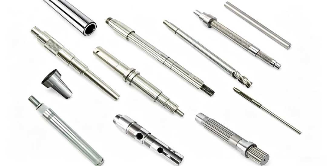
A transmission shaft made from heat-treated 4140 alloy steel included multiple stepped diameters and bearing journals. The main challenge was maintaining concentricity after heat treatment. Between-centers turning with steady-rest support, followed by finish grinding on the bearing journals, produced stable runout and reliable bearing fits.
High-Volume Motor Shaft
A motor shaft machined from 1215 free-machining steel required consistent quality across thousands of parts. In-process gauging and automatic tool compensation improved dimensional consistency throughout production while reducing variation caused by tool wear.
Medical Connector Shaft
A small 316L stainless steel shaft with grooves, threads, and a through-hole presented a high risk of deflection. Drilling the through-hole before finish turning and using light cutting passes helped maintain dimensional accuracy across the production batch.
Although the applications were different, the same principle applied to all three projects: stable workholding, appropriate machining methods, and a process matched to the shaft geometry produced better results than relying on tighter tolerances alone.
7. How to Review a Shaft Drawing Before Quoting
A careful drawing review often prevents machining problems before production begins. Features that appear reasonable on the drawing may increase machining difficulty, inspection time, or production cost once the shaft reaches the shop floor.
Uzunluk-Çap Oranı
Long shafts require adequate support during machining. When the unsupported length becomes too large, deflection affects diameter accuracy and straightness. Center holes and suitable steady-rest contact areas should be included whenever long-shaft machining is expected.
Functional Tolerances
Diameter alone rarely defines shaft performance. Rotating shafts should include appropriate runout or concentricity requirements where functional performance depends on bearing or seal alignment. Tolerances should reflect the actual application rather than applying unnecessarily tight values to every feature.
Shaft Geometry
Shoulder transitions, bearing seats, and other critical features should allow adequate tool access during machining. Sharp internal transitions increase stress concentration, while insufficient tool clearance complicates manufacturing and inspection.
Malzeme Seçimi
Material specifications should be reviewed together with production volume and service requirements. Free-machining steels, alloy steels, and stainless steels offer different balances of strength, corrosion resistance, and machinability. The most suitable material is not always the strongest one.
Small adjustments during the drawing review often reduce machining complexity, improve process stability, and lower production cost before the first part is ever machined.
Çözüm
Producing a precision shaft involves much more than holding dimensional tolerances. Material selection, shaft geometry, machining methods, workholding, and inspection all influence how the finished shaft performs in service.
For this reason, every precision shaft project at Beşka starts with a drawing review rather than the machine. We look at how the part will be manufactured, supported, inspected, and assembled before deciding how it should be machined. Addressing these details early usually leads to a more stable process and a more reliable finished part.
 Turkish
 English
 Hebrew
 French
 Russian
 German
 Spanish
 Portuguese