


A hole that stops inside a part rather than going all the way through may seem unremarkable at first glance. Yet in many components, this type of hole can determine how well a fastener holds, how a seal performs, or whether a surface stays intact under stress.
Blind holes are chosen when maintaining the opposite surface is critical or when precise alignment is required. Factors such as depth, diameter, and bottom shape directly affect performance and manufacturability.
This article examines the technical aspects of blind holes, including design principles, machining considerations, material-specific challenges, and best practices, revealing why this subtle feature plays a key role in precision engineering.
1. What Is A Blind Hole?

A blind hole is a hole that does not extend entirely through the material; the bottom of the hole terminates within the workpiece. This simple distinction has significant implications:
- Structural Considerations: Because the bottom material remains intact, blind holes preserve part strength and stiffness, unlike through holes, which can reduce cross-sectional area and weaken components.
- Hole Depth and Diameter: Engineers must carefully define the depth and diameter to accommodate fasteners or inserts without exceeding machining limits. Excessive depth relative to diameter increases tool stress and chip evacuation difficulty.
- Bottom Shape: Common bottom profiles include flat, rounded, and tapered. Flat bottoms provide stable surfaces for threaded inserts, while rounded bottoms reduce stress concentration in metals. Tapered bottoms facilitate smooth chip flow and insertion of certain fasteners.
- Wall Quality and Surface Finish: Maintaining consistent wall thickness, surface roughness (typically Ra 0.8–1.6 µm for general metal parts), and concentricity ensures reliable thread engagement and avoids stress risers.
These characteristics form the foundation for designing blind holes that are both functional and manufacturable.
2. Geometry Considerations of Blind Holes

The geometry of a blind hole strongly affects performance, manufacturability, and reliability. Key considerations include:
Depth-to-Diameter Ratio
Exceeding a ratio of 5:1 in metals or 3:1 in plastics increases tool deflection, friction, and chip accumulation. Deep holes often require peck drilling, step drilling, or specialized long-reach drills to maintain accuracy and prevent damage.
Bottom Profile
Flat bottoms provide stable seating for threaded inserts and precise assemblies. Rounded bottoms distribute stress more evenly in structural components, reducing the risk of microcracks. Tapered bottoms can aid chip evacuation and reduce burr formation.
Wall Thickness and Concentricity
Uniform wall thickness prevents localized stress concentrations. Misalignment or tapering from tool deflection can compromise assembly fit, especially in components using dowels or locating pins.
Stepped or Compound Holes
Blind holes with multiple diameters or depth steps accommodate different fasteners or inserts. These require careful sequencing, precise drilling, and reaming to maintain tolerance. Cutting parameters and coolant application should be adjusted for each step to avoid surface defects or dimensional errors.
Each of these geometric factors influences tool life, surface quality, and part functionality. Careful planning ensures blind holes perform as intended without compromising structural integrity.
3. Design Considerations for Blind Holes
Designing a blind hole requires careful attention to mechanical, functional, and manufacturing constraints, with several aspects directly affecting performance and machinability.
- Depth and Diameter Selection: Depth-to-diameter ratios above 5:1 in metals or 3:1 in plastics increase tool deflection, friction, and chip accumulation. Very deep holes may need peck drilling, step drilling, or long-reach drills to maintain accuracy and surface quality.
- Threaded Blind Holes: Thread engagement must match material strength and fastener size. For example, an M6 screw in aluminum typically needs 10–12 mm of thread depth for full load capacity. Proper chamfering and pilot diameters improve thread formation and reduce stress concentrations.
- Material-Specific Adjustments: Hard metals such as stainless steel or titanium require slower cutting speeds and coated tools to prevent galling. Plastics may need pilot holes and controlled feed rates to avoid cracking or melting, while heat management ensures dimensional stability.
- Stress and Clearance: Abrupt hole terminations or excessive depth can create stress concentrations. Small chamfers, fillets, or slight tapers at the bottom help distribute stress and protect the surrounding material. Adequate clearance between the fastener and the hole wall prevents binding.
- Functional Alignment: Blind holes used for guiding or locating components must maintain tight concentricity, often within ±0.05 mm for precision assemblies. Accurate fixturing and careful tool control are essential to ensure consistent alignment and proper assembly fit.
These considerations help ensure blind holes function reliably while maintaining structural integrity and manufacturability.
4. Manufacturing Challenges and Techniques

Machining a blind hole is more complex than creating a through hole. Limited tool access and chip accumulation create unique challenges that must be addressed to ensure precision and surface quality.
| Meydan okumak | Common Techniques | Key Considerations |
| Chip Evacuation | Peck drilling, step drilling | Prevents tool breakage and surface damage |
| Araç Seçimi | Spiral drill bits, step drills, reamers | Tool rigidity, flute design, and material compatibility are critical |
| Bottom Surface Control | Reaming, light milling | Ensures flat or precise bottom for tight tolerances or threaded holes |
| Alignment and Fixturing | Accurate fixturing, slow feed rates | Maintains concentricity and reduces deflection in deep holes |
| Advanced Techniques | CNC deep-hole drilling, micro-drilling, peck cycles | Required for small-diameter or very deep blind holes to maintain accuracy |
Effective management of these factors helps achieve consistent blind hole quality while avoiding common machining problems.
5. Material-Specific Considerations of Blind Holes
Not all materials behave the same when machining blind holes. Factors like heat sensitivity, chip formation, and surface integrity can vary greatly between metals, plastics, and composites.
- Metals: Steel and aluminum are commonly used. Steel requires slower spindle speeds, proper coolant, and sharp coated tools to prevent work hardening, excessive heat, and tool wear. Aluminum, being softer, is prone to chip clogging and smearing, so peck drilling, high-quality fluted drills, and controlled feed rates are essential to maintain surface finish and dimensional accuracy.
- Plastics: Thermoplastics such as ABS, POM, or polycarbonate are highly sensitive to heat. High spindle speeds, low feed rates, or insufficient coolant can cause melting, burr formation, or hole deformation. Pilot holes, step drilling, and moderate cutting speeds help reduce thermal stress and maintain hole geometry.
- Composites and Exotic Materials: Materials like carbon fiber, GFRP, or titanium demand specialized coated drills, reduced feed rates, and precise chip evacuation. In composites, delamination, fiber pull-out, and surface fraying are common risks, while titanium’s low thermal conductivity requires careful speed and feed control to avoid work hardening and tool wear.
Different materials respond uniquely to cutting forces, heat, and chip formation. Selecting the right tool, feed rate, and cooling method for each material ensures that blind holes retain dimensional accuracy, surface quality, and structural integrity.
6. Practical Applications of Blind Holes
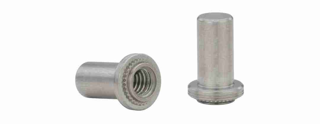
In many components, blind holes are chosen not just for convenience but to meet specific functional and structural requirements. Their use spans fastening, alignment, sealing, and precision assembly.
- Fastener Installation: Blind holes anchor screws, bolts, or threaded inserts without breaking through the opposite surface. This preserves structural integrity and prevents leakage in pressure-sensitive parts. Correct thread depth and chamfering are crucial to avoid stripping or uneven load distribution.
- Guiding and Locating: Precision assemblies rely on blind holes to position alignment pins, dowels, or locating features. Maintaining concentricity and tight tolerances (often ±0.05 mm for high-precision applications) ensures consistent assembly performance and reduces wear on mating components.
- Sealing Applications: Blind holes can serve as reservoirs, anchor points, or pockets for O-rings and hydraulic or pneumatic seals. Proper depth and diameter are critical to prevent deformation, leakage, or insufficient sealing pressure.
- Molded Plastics and Inserts: In plastic components, blind holes allow metal inserts to be placed without compromising part strength. They prevent through-holes that could weaken the component or create unwanted flow paths during molding. Tool selection and pilot holes help maintain hole accuracy and surface finish.
- Industry Examples: Aerospace structures use blind holes to retain strength while reducing weight. Automotive engines often employ them for threaded inserts in aluminum blocks. Consumer electronics use blind holes for compact assemblies, enabling fasteners to secure components without protruding through delicate surfaces.
By tailoring blind hole design to its intended function, engineers can achieve strong, precise, and reliable components across a wide range of materials and industries.
7. Common Engineering Mistakes
Even small errors in blind hole design or machining can lead to significant problems in component performance. The most frequent mistakes include:
- Excessive Depth: Drilling too deep increases tool deflection, heat buildup, and chip accumulation. This can cause poor surface finish, tapering, or even tool breakage. Using peck drilling or multiple passes helps manage depth safely.
- Ignoring Bottom Surface Quality: Uneven or rough bottoms compromise seating for threaded inserts, fasteners, or sealing elements. Secondary operations such as reaming, light milling, or chamfering are often needed to ensure a flat, uniform bottom.
- Improper Thread Engagement: Threads that are too shallow may strip under load, while overly deep threads can weaken surrounding material. Correct engagement depth must be calculated based on screw diameter, material strength, and expected load.
- Misaligned Holes: Poor concentricity or off-center drilling affects assembly alignment and fastener performance. Precision fixturing and careful tool control are essential to maintain alignment within tight tolerances.
- Neglecting Material Behavior: Plastics may shrink, warp, or crack if feed rates, speeds, or pilot holes are incorrect. Metals such as stainless steel or titanium can gall, work-harden, or generate excessive heat if cutting parameters are ignored.
Attention to these common pitfalls, combined with proper planning, tool selection, and machining strategy, ensures blind holes perform reliably and maintain component integrity.
8. Engineering Best Practices for Blind Holes
To ensure reliable blind hole performance, engineers should consider the following:
- Maintain Realistic Depth-to-Diameter Ratios: Keep ratios ≤5:1 for metals and ≤3:1 for plastics. For deeper holes, use peck drilling or step drills to prevent tool deflection and chip accumulation.
- Optimize Bottom Surface: Step drilling, reaming, or slight tapering helps achieve flatness and reduce stress. Chamfers improve thread formation and prevent fastener damage.
- Ensure Wall Quality and Concentricity: Use rigid fixturing, controlled feed rates, and appropriate drill geometry to maintain uniform walls and alignment, particularly in deep or high-precision holes.
- Threaded Holes: Limit thread depth according to material strength. Pilot holes and chamfers help prevent stripping and burr formation.
- Manage Chips Effectively: Peck drilling, progressive depth cuts, and coolant ensure smooth chip evacuation, protect tools, and maintain surface finish.
- Adapt to Material Properties: Adjust spindle speed, feed rate, and tool coatings based on the workpiece. Metals may require coated drills; plastics need careful heat control to avoid deformation.
Following these best practices ensures blind holes remain precise, structurally sound, and manufacturable.
Çözüm
Blind holes may appear simple, yet their correct design and execution significantly affect component performance, durability, and assembly precision. Small details such as depth ratios, bottom surface quality, concentricity, and material-specific considerations often determine whether a part functions reliably or faces unexpected failures. Applying careful design, precise machining, and material-aware practices helps minimize defects and optimize performance.
For projects where precision and reliability are critical, consulting an experienced manufacturing partner like the Beska team who understands blind hole challenges can ensure functional components and reduce costly rework.
Kaynaklarımıza Daha Derinlemesine Dalın
İçgörü dolu okumalar için, sizin için özel olarak önerilen makalelerden oluşan bir liste hazırladık:
 Turkish
 English
 Hebrew
 French
 Russian
 German
 Spanish
 Portuguese