


An undercut is any feature that a standard end mill cannot machine with a straight vertical or horizontal approach. Instead, the tool’s shank or holder would interfere with the workpiece before the cutting edges can reach the target surface. Features such as retaining ring grooves, dovetail slides, and T-slots are all common examples.
Although many undercut geometries exist, most CNC machined parts use four common types: internal grooves, dovetails, T-slots, and thread reliefs. Each serves a different engineering purpose and requires different tooling, machining strategies, and design considerations. A feature that appears simple in CAD can require specialized cutters, additional setups, or significantly longer machining time once it reaches the shop floor.
This guide explains the four most common types of machining undercuts, how each is manufactured, what tooling is required, and the practical design guidelines that help reduce machining cost, improve manufacturability, and avoid unnecessary production risks.
1. What Exactly Makes a Feature an Undercut?
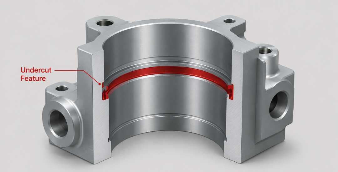
An undercut is any feature that a standard end mill cannot machine with a straight vertical or horizontal approach. If the tool’s shank or holder interferes with the workpiece before the cutting edges reach the target surface, the feature is considered an undercut.
Because conventional end mills require direct tool access, blocked features must be machined using a different approach. Depending on the geometry, this may involve reduced-neck cutters, dovetail cutters, lollipop cutters, multi-axis machining, or processes such as EDM. As tool accessibility decreases, machining complexity, setup time, and production cost generally increase.
For designers, the important point is that an undercut is defined by tool accessibility rather than appearance. A narrow groove deep inside a bore may look like a simple feature on a drawing, but it can require specialized tooling, additional setups, or even a different machining process. Evaluating undercut features early in the design stage is often the simplest way to improve manufacturability and avoid unnecessary production cost.
2. The Four Most Common Types of Undercuts
While many undercut geometries exist in specialized applications, four types appear most frequently in production CNC machining: internal grooves, dovetails, T-slots, and thread reliefs. Each serves a different engineering purpose, presents different machining challenges, and requires a different manufacturing strategy.
| Undercut Type | Typical Application | Main Machining Challenge |
| Internal Grooves | Retaining rings, seal grooves | Tool rigidity |
| Dovetails | Sliding mechanisms, machine ways | Angle accuracy |
| T-Slots | Fixture tables, clamping systems | Chip evacuation |
| Thread Reliefs | Thread runout | Width control |
Internal Grooves and Recesses
Internal grooves are commonly used for retaining rings, seals, and snap rings. Their function is simple: to provide a recessed seat inside a bore without increasing the overall outside dimensions of the part.
The main challenge is limited tool access. The cutter must enter the bore before moving sideways to machine the groove, which usually requires a lollipop cutter or a reduced-neck grooving tool. The smaller the tool neck, the lower its rigidity and the greater the risk of deflection or breakage.
In one project, a 0.062-inch-wide groove inside a 0.75-inch bore required a lollipop cutter with only a 0.040-inch neck. The reduced rigidity forced feed rates down to approximately 40% of normal, significantly increasing cycle time while limiting tool life.
Keeping the groove depth-to-width ratio reasonable and specifying corner radii whenever possible both improve manufacturability and reduce tooling risk. In practice, tool rigidity usually becomes the limiting factor long before machine capability.
Dovetail Undercuts
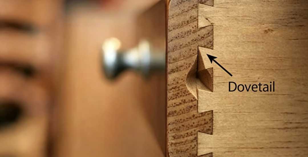
Dovetail undercuts are widely used in slide mechanisms, locking assemblies, and machine tool ways where accurate guidance and secure mechanical engagement are required.
Unlike a standard slot, a dovetail must be machined with a dedicated dovetail cutter that enters vertically before cutting sideways along the angled walls. Maintaining a consistent angle over the entire feature is the greatest challenge, since tool wear, runout, and deflection can all affect the final fit.
For most production parts, an angular tolerance of around ±0.5° is practical. Tighter tolerances should be specified only when required by the application because they increase inspection effort, tool replacement frequency, and machining cost.
For dovetail features, maintaining a consistent angle is often more difficult than machining the feature itself.
T-Slots
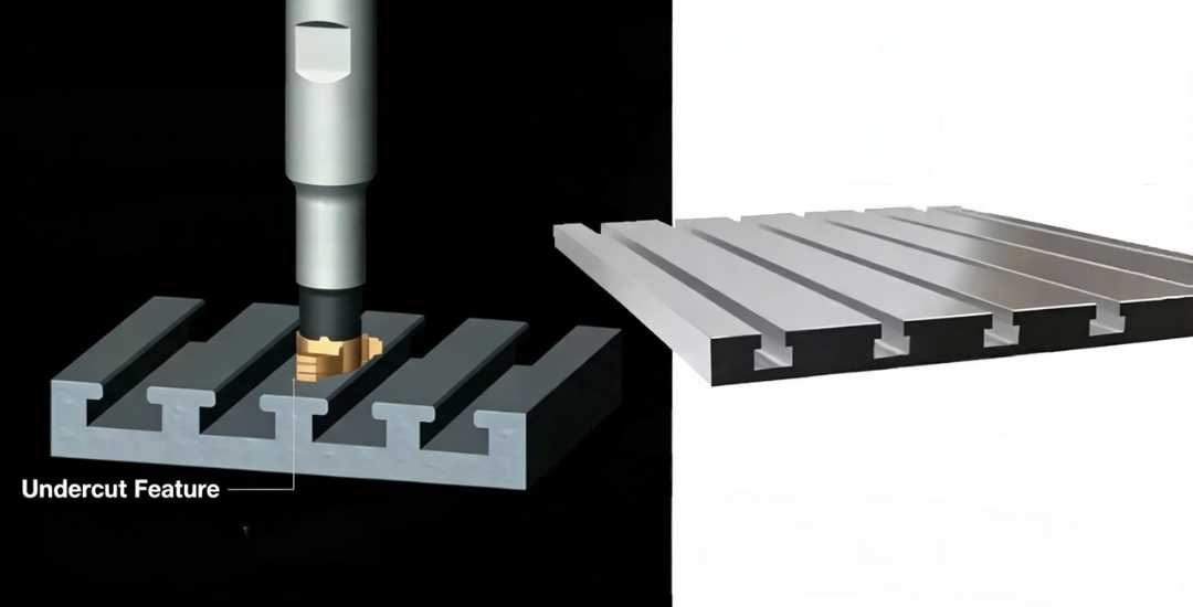
T-slots are commonly found on fixture plates, machine tables, and workholding systems where bolts or clamps must slide into position while remaining securely retained.
Machining normally requires two operations: first milling a straight slot with a standard end mill, followed by machining the undercut using a dedicated T-slot cutter. As slot depth increases, chip evacuation becomes progressively more difficult, while the reduced shank of the cutter is subjected to greater bending loads.
Through-tool coolant or high-pressure air significantly improves chip removal. In many production environments, periodically retracting the cutter to clear chips slightly increases cycle time but greatly reduces the risk of tool breakage and scrap.
Reliable chip evacuation is often the deciding factor between stable production and repeated tool failures.
Thread Relief Undercuts
Thread relief undercuts are narrow grooves machined at the end of a threaded section, allowing the threading tool to exit cleanly without colliding with a shoulder. They ensure the thread profile is fully formed right up to the end of the thread.
Although thread reliefs are among the simplest undercuts to machine, their width still requires careful control. A relief that is too narrow prevents proper tool runout, while an oversized relief unnecessarily weakens the threaded section.
Standard grooving or form tools can usually hold relief widths within ±0.005 inch, making thread reliefs one of the lowest-cost undercut features in CNC machining.
A properly sized thread relief simplifies machining while maintaining full thread performance.
3. Manufacturing Methods for Undercuts
The best machining method depends on the undercut geometry, material, production volume, and available equipment. In most cases, specialized cutters are the most practical solution, while multi-axis machining and EDM are reserved for features that cannot be produced efficiently with conventional tooling.
Specialized Cutting Tools
Specialized cutters, including lollipop cutters, T-slot cutters, and dovetail cutters, are the standard solution for most undercuts in CNC machining. They are readily available from major tooling suppliers and are usually the most economical option for production.
Their main limitation is reduced rigidity. Compared with a standard end mill, these cutters require lighter radial engagement and lower feed rates to control deflection and extend tool life. As a result, machining undercuts is typically slower than machining open features with conventional tooling.
Usinage multi-axes
When undercuts are difficult to reach with dedicated cutters, 4-axis or Usinage 5 axes can often provide a better solution. By rotating or tilting the workpiece, the machine presents the feature to a standard end mill, improving tool rigidity and reducing the need for specialized tooling.
This approach is most cost-effective for complex components containing multiple undercuts or features machined from several directions. For simple parts with a single undercut, however, the additional programming and machine cost are rarely justified.
Usinage par décharge électrique (EDM)
For deep, narrow, or highly complex undercuts that rotating tools cannot access, EDM provides an effective alternative. Because material is removed by electrical discharge rather than cutting forces, tool deflection is eliminated, making EDM well suited for sharp internal corners and intricate geometries.
The trade-off is productivity. EDM is considerably slower than conventional milling and usually involves higher tooling and machine costs, making it more suitable for low-volume or high-value components.
In some cases, a small design change like relocating a groove or adding machining access, which can eliminate the need for EDM entirely. Evaluating manufacturability during the design stage often provides the greatest opportunity for cost reduction.
For most production parts, specialized cutters remain the preferred solution. Multi-axis machining and EDM become worthwhile only when the geometry makes conventional tooling impractical or inefficient.
4. Design Guidelines to Avoid Costly Mistakes
Most undercut machining problems originate during the design stage rather than on the shop floor. Small design changes often improve tool accessibility, reduce machining complexity, and lower production cost without affecting part function.
Provide Adequate Tool Access
The cutting tool must be able to reach the feature without the shank interfering with the workpiece. For internal grooves and T-slots, excessive depth relative to tool diameter quickly reduces tool rigidity. As a practical guideline, keep the cutting depth below three times the tool diameter whenever possible.
Add Corner Radii
Avoid sharp internal corners unless they are functionally required. A corner radius of at least 0.020 in allows stronger tooling, improves tool life, and reduces the risk of chipping during machining.
Specify Realistic Surface Finish Requirements
Undercuts generally produce rougher surfaces than open machining because of limited tool rigidity and interrupted cutting. A finish of around 125 μin Ra is practical for most applications, while 63 μin Ra usually requires additional finishing passes, rigid setups, and tighter process control.
Consider Material During Design
Material selection directly affects undercut machinability. Stainless steel and other high-strength alloys generate higher cutting forces and reduce tool life compared with aluminum. Considering the material early in the design stage helps produce more realistic cost estimates and machining strategies.
Many undercut features become expensive not because of the geometry itself, but because the design limits tool access or requires unusually slender cutters. Improving accessibility and keeping feature proportions practical is often the simplest way to reduce machining cost and improve manufacturability.
5. Cost Implications: A Practical Example
Undercuts increase manufacturing cost in three primary ways: specialized tooling, longer machining cycles, and higher scrap risk. The balance between these factors often determines whether an undercut can be produced economically.
A hydraulic manifold we machined contained six internal grooves, each requiring a 0.070-inch-wide groove inside a 0.50-inch bore at a depth of 1.0 inch. During the initial production run, a standard lollipop cutter broke on the second part, resulting in a scrapped component. Replacing the cutter with a more robust design and reducing the feed rate from 15 in/min to 8 in/min increased cycle time by approximately 40%, but eliminated subsequent tool failures and stabilized production.
This example illustrates that tooling cost should be evaluated together with tool life and process stability rather than as an isolated expense. A more expensive cutter often reduces the overall cost of production by improving reliability and lowering scrap rates.
Many of these costs can also be avoided before machining begins. A Design for Manufacturability (DFM) review frequently identifies opportunities to improve tool access, simplify undercut geometry, or relax unnecessary tolerances while design changes are still inexpensive. Addressing these issues early usually has a much greater impact on production cost than optimizing cutting parameters after machining has started.
6. Choosing the Right Undercut Type
No single undercut type is suitable for every application. The right choice depends on the part’s function, machining complexity, and production cost. The comparison below summarizes the key differences between the four most common undercut types.
Undercut Type | Typical Tool | Common Application | Key Limitation | Relative Cost Impact |
Internal groove | Lollipop cutter, grooving tool | Retaining rings, seals | Tool access, neck rigidity | Modéré |
Dovetail | Dovetail cutter | Slides, guides, locks | Angle accuracy, surface finish | Moderate-High |
T-slot | T-slot cutter | Clamping, fixtures | Chip evacuation, breakage | Modéré |
Thread relief | Grooving tool | Threaded shoulders | Width control, depth | Faible |
A more complex undercut does not necessarily produce a better design. Whenever two solutions provide the same mechanical function, the geometry that is easier to machine is usually the better engineering choice. Reducing unnecessary machining complexity improves production efficiency, lowers cost, and makes dimensional consistency easier to maintain in volume production.
Conclusion
Undercut machining is not defined by geometry alone. Successful results depend on balancing part function, tool accessibility, machining strategy, and manufacturing cost. Choosing the right undercut early in the design stage often has a greater impact on production efficiency than optimizing cutting parameters after machining begins.
Designing with manufacturability in mind helps reduce unnecessary tooling, simplify machining, and improve production consistency. Features that allow better tool access are generally easier to machine, require fewer setups, and provide more stable results throughout production.
At Beska, we review undercut features during the DFM stage to evaluate tool accessibility, machining strategy, and production feasibility before manufacturing begins. Whether the part requires standard internal grooves or complex multi-axis undercuts, our engineering team helps identify practical machining solutions that balance performance, cost, and manufacturability.
Deeper into Our Resources
Pour des lectures enrichissantes, nous avons sélectionné pour vous une liste d'articles recommandés :
 French
 English
 Hebrew
 Turkish
 Russian
 German
 Spanish
 Portuguese