


UN sheet metal part can look correct in CAD and still come off the press brake with flange lengths or hole positions that do not match the drawing. In many cases, the problem starts with how the bend is unfolded into a flat pattern.
During bending, the neutral axis shifts away from the middle of the sheet, and K-factor describes its position relative to the material thickness. That value affects bend allowance and therefore the final flat-pattern dimensions. Material, bend radius, tooling, and forming method can all influence the result, which is why a single default K-factor does not work equally well for every bending condition.
1. What Is the Neutral Axis?

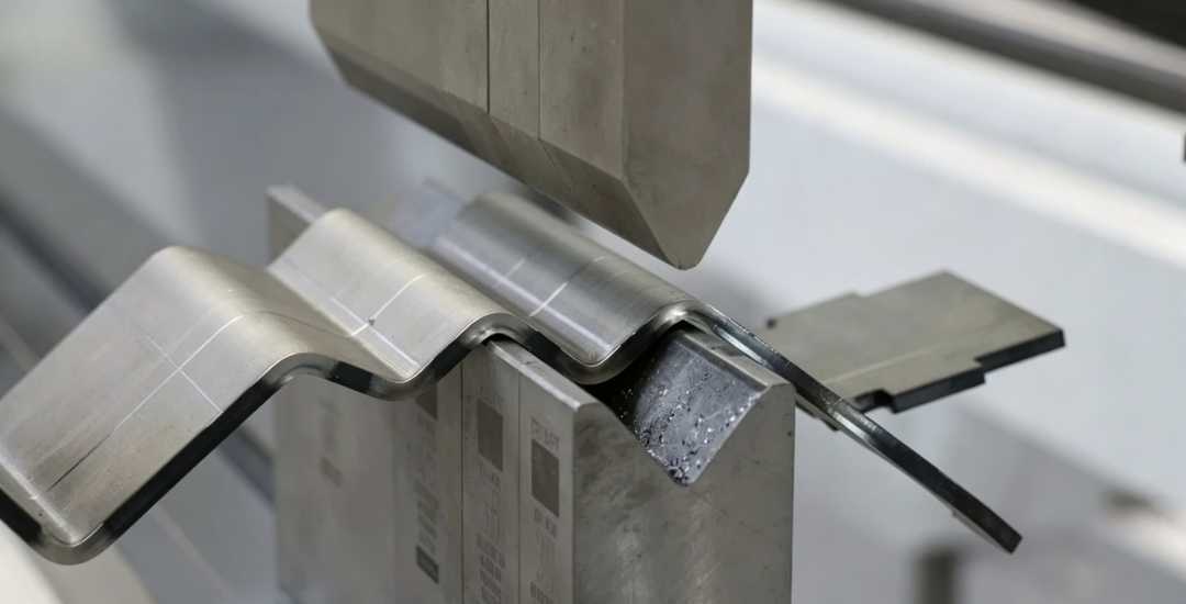
When sheet metal is bent, the material on the outside of the bend is stretched while the material on the inside is compressed. Between these two regions lies the neutral axis, where the longitudinal strain is approximately zero.
In a flat, uniform sheet, this reference position is near the middle of the thickness. During plastic bending, the neutral axis generally shifts toward the inside of the bend. K-factor describes the location of this neutral axis relative to the material thickness.
This matters because the length of the neutral axis through the bend is used to calculate bend allowance. Its position therefore affects the flat-pattern length needed to produce the required flange dimensions after bending.
2. What Is the K-Factor?
The K-factor describes the position of the neutral axis through the sheet thickness. It is calculated as the distance from the inside surface of the bend to the neutral axis divided by the material thickness.
K = t / T
Where:
- t = distance from the inside surface to the neutral axis
- T = material thickness
For example, if the neutral axis is located at 44% of the material thickness measured from the inside surface, the K-factor is 0.44.
K-factor values are commonly expressed between about 0.30 and 0.50, depending on the material and bending conditions. A value of 0.50 places the neutral axis at the middle of the sheet thickness, while a lower value places it closer to the inside surface.
Because the neutral-axis position changes with the actual bending conditions, the K-factor should be treated as a process-dependent value rather than a fixed material property.
3. How Forming Method and Bend Radius Affect K-Factor
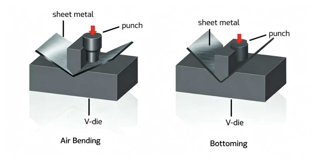
The K-factor is influenced by the actual bend geometry, especially the relationship between the inside bend radius and material thickness. A change in tooling or forming method can change the inside radius, which in turn affects the neutral-axis position used in flat-pattern calculations.
| Forming Method | Typical Bend Behavior | Effect on K-Factor Calculations |
| Flexion de l'air | Inside radius depends strongly on the V-die opening, material, and tooling setup | Bend data may change when the die opening or tooling changes |
| Toucher le fond | Material is formed more closely to the punch and die geometry | Bend radius is generally more controlled, but material and tooling still affect the result |
| frappe de monnaie | Very high pressure forces the material closely into the tooling | Can reduce springback, but requires much higher forming force |
The radius-to-thickness ratio (R/T) is also important. A tight bend and a large-radius bend do not deform the material in the same way, so the same K-factor should not automatically be assumed for both.
For production parts, the bend data used in CAD should match the material, thickness, inside radius, and tooling actually used on the press brake. If any of these conditions change, the flat pattern may need to be verified again.
4. How K-Factor Is Used in Bend Allowance
K-factor becomes useful when calculating bend allowance, which represents the length of the neutral axis through the bend. This value is used when developing the flat pattern of a bent sheet metal part.
The bend allowance formula is:
BA = A × (R + K × T)
Where:
- BA = bend allowance
- A = bend angle in radians
- R = inside bend radius
- K = K-factor
- T = material thickness
If the bend angle is given in degrees:
BA = (π / 180) × A × (R + K × T)
For example, a 90° bend and a 45° bend with the same material thickness, inside radius, and K-factor will have different bend allowances because the neutral-axis arc length changes with the bend angle.
Bend allowance can then be used together with flange geometry to determine the required flat length. Where bend deduction is used instead, it can be calculated from the outside setback and bend allowance:
BD = 2 × OSSB − BA
with: OSSB = tan(A / 2) × (R + T)
The same bend-angle convention should be used consistently throughout the calculation.
5. K-Factor vs Y-Factor
K-factor and Y-factor are both used in sheet metal bend calculations, but they are expressed differently. In systems that use the common relationship between the two:
Y = K × π / 2
K-factor describes the position of the neutral axis as a ratio of material thickness, while Y-factor is another parameter used by some CAD and sheet metal calculation systems.
For most design work, the important point is consistency. The value and calculation method used in CAD should match the bend table or manufacturing data used for the actual material, radius, and tooling. Switching between K-factor and Y-factor does not correct an inaccurate flat pattern if the underlying bend data is wrong.
6. What Affects K-Factor in Production
K-factor is influenced by the actual bending conditions rather than by material grade alone. Changes in material, thickness, bend geometry, or tooling can all affect the neutral-axis position and the resulting flat pattern.
Material and Thickness
Different alloys, strength levels, and tempers respond differently during bending. Material thickness also matters because it changes the relationship between the sheet and the bend radius. For this reason, a K-factor established for one material and thickness should not automatically be applied to another.
Bend Radius and Tooling
The actual inside radius has a direct influence on the bend geometry. Changes in die opening, punch geometry, tooling condition, or press-brake setup can therefore change the bend data used for flat-pattern development.
Material Variation and Grain Direction
Material properties can vary between grades, tempers, and production lots. Grain direction may also influence bending behavior, especially where formability and springback are sensitive to bend orientation.
For repeat production, it is more reliable to maintain bend data for the actual combinations of material, thickness, bend radius, and tooling used in the shop, and to verify the flat pattern when those conditions change.
7. How to Determine K-Factor in Production
A practical way to establish a K-factor for a specific bending setup is to run a test bend using the same material, thickness, tooling, and press-brake conditions planned for production.
- Step 1: Cut a flat test blank and record its dimensions.
- Step 2: Bend the sample to the required angle using the intended tooling and machine setup.
- Step 3: Measure the formed flange dimensions and the actual inside bend radius.
- Step 4: Determine the bend allowance from the measured geometry using a consistent dimensional reference.
- Step 5: Calculate the K-factor from the bend allowance equation: K = [BA / (A × T)] − (R / T)
Where:
- BA = measured bend allowance
- A = bend angle in radians
- T = material thickness
- R = inside bend radius
This equation comes directly from: BA = A × (R + K × T)
The resulting K-factor reflects the actual combination of material, thickness, bend radius, tooling, and machine setup. For repeat production, these measured values can be stored in a bend table and reused when the same bending conditions apply.
8. K-Factor Calculation Example
Consider a 90° bend in 1.5 mm sheet metal with a 1.5 mm inside radius.
The bend angle in radians is: 90 × (π / 180) = 1.5708
Using a K-factor of 0.446:
- BA = 1.5708 × (1.5 + 0.446 × 1.5)
- BA ≈ 3.41 mm
Using a K-factor of 0.33:
- BA = 1.5708 × (1.5 + 0.33 × 1.5)
- BA ≈ 3.13 mm
The difference is about 0.27 mm for a single bend. If the same difference occurs across four bends, the total flat-development difference can approach 1.1 mm.
For parts with several bends, short flanges, or closely positioned mounting holes, this difference can become significant. The example shows why the K-factor used in CAD should reflect the actual material, bend radius, and tooling rather than being treated as a fixed default value.
9. Typical K-Factor Starting Values
Published K-factor values can be useful during early design, but they should be treated as starting points rather than fixed material constants. The actual value can change with material condition, thickness, inside bend radius, tooling, and forming method.
| Matériel | Common Starting Range |
| Mild steel | ~0.40–0.45 |
| Acier inoxydable | ~0.40–0.50 |
| alliages d'aluminium | ~0.33–0.45 |
| Copper and brass | Varies with alloy and temper |
These ranges are only approximate. Two parts made from the same material can require different K-factors if the thickness, bend radius, tooling, or forming method changes.
For production work, bend-test data or a validated shop bend table is more reliable than selecting a K-factor from a general material table.
10. K-Factor vs Bend Deduction
K-factor and bend deduction are both used to develop sheet metal flat patterns, but they describe different parts of the calculation.
| Méthode | What It Represents | Typical Use |
| Facteur K | Neutral-axis position relative to material thickness | Bend allowance calculations and CAD bend tables |
| Bend Deduction | Amount subtracted from the sum of outside flange dimensions to obtain the flat length | Shop bend tables and direct flat-pattern calculations |
K-factor is used to calculate bend allowance, while bend deduction converts the formed outside dimensions directly into a flat length. The two methods are related through bend allowance and outside setback rather than being separate ways of describing the material itself.
In production, either method can work when the values are based on the actual material, bend radius, tooling, and bend angle. The important point is that the CAD model and shop bend data use the same calculation method and validated bending conditions.
Conclusion
K-factor describes the position of the neutral axis through the sheet thickness and directly affects bend allowance and flat-pattern dimensions. It should not be treated as a fixed material constant, since the actual value can change with material condition, thickness, inside bend radius, tooling, and forming method.
For production parts, the bend data used in CAD should match the actual forming conditions as closely as possible. Test bends and validated bend tables are especially useful when flange lengths, hole positions, or multiple bends leave little room for accumulated flat-pattern error.
If your sheet metal drawing includes critical bend dimensions, Beska can review the material thickness, bend radius, K-factor, and flat-pattern setup together before production, helping identify potential unfolding or bend-allowance issues before the blanks are cut.
 French
 English
 Hebrew
 Turkish
 Russian
 German
 Spanish
 Portuguese