


A sink mark often appears as a shallow depression on the surface of an injection-molded part, especially opposite a rib, boss, or other locally thick section. The cavity may fill completely and the part may still develop visible sinking as the plastic cools and shrinks.
These defects are not always caused by one molding parameter. Part geometry, material shrinkage, gate and packing conditions, and mold cooling can all influence whether a sink mark forms and how severe it becomes. Process adjustments may solve some cases, while others require changes to the part or mold design.
This article explains how sink marks form, the main factors that cause them, how part and mold design affect the risk, and how to troubleshoot recurring sink marks during molding.
1. What Are Sink Marks in Injection Molding?
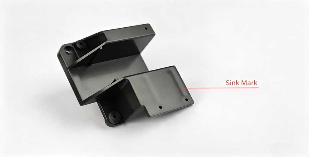
Sink marks are localized depressions that develop on the surface of an injection-molded part as the plastic cools and shrinks. They commonly appear opposite ribs, bosses, thick fillets, or other areas where the local material section is thicker than the surrounding wall.
During molding, the plastic in contact with the mold surface cools and solidifies first, while material inside thicker sections remains hot for longer. As the inner material continues to shrink, packing pressure must supply additional melt to compensate for the lost volume. If that compensation becomes insufficient after the gate freezes or the outer layer has already stiffened, the surface can be pulled inward and form a visible sink mark.
Sink Marks vs. Shrinkage Voids
Sink marks and internal voids can result from the same underlying volumetric shrinkage, but they appear differently. A sink mark forms when the outer surface moves inward as the interior shrinks. If the surface remains rigid enough to resist that movement, the shrinkage may instead leave an internal cavity or void inside the thicker section.
This is why sink marks are often concentrated around local material buildup rather than distributed evenly across the entire molded part.
2. What Causes Sink Marks?
Sink marks usually develop when local shrinkage is greater than the amount of material that can be compensated during packing and cooling. The defect may come from part geometry, material behavior, gate and packing conditions, cooling, or a combination of these factors.
Géométrie des pièces
Local thick sections are one of the most common design-related causes of sink marks. Thick ribs, bosses, fillets, intersections, and abrupt wall-thickness changes cool more slowly than the surrounding wall and create areas of concentrated volumetric shrinkage.
Even when the nominal wall thickness is reasonable, several features meeting in one location can create hidden material buildup and a local hot spot.
Material Shrinkage
Different thermoplastics have different molding shrinkage characteristics, and this affects how sensitive a part is to sink marks. Resin grade, filler content, fiber orientation, moisture condition, and material consistency can all influence shrinkage behavior.
Filled materials often show lower overall shrinkage than their unfilled counterparts, but fillers can also introduce directional shrinkage and other dimensional effects. Material data therefore needs to be considered together with part geometry and molding conditions.
Gate and Packing Conditions
Packing pressure must continue supplying material as the molded part shrinks after filling. If packing pressure is too low, holding time is too short, or the gate freezes before a thick section has been adequately packed, the remaining shrinkage may appear as a sink mark.
Gate position and size also matter because they determine how effectively packing pressure can reach sink-prone areas.
Cooling Conditions
Uneven cooling can increase the temperature difference between thick and thin regions of the part. Areas that remain hot for longer continue shrinking after surrounding sections have already become relatively rigid.
Cooling-channel layout, local heat concentration, mold temperature, and part thickness all influence this behavior. A persistent sink mark therefore needs to be evaluated as a combined geometry, packing, and cooling problem rather than treated only as a machine-setting issue.
3. How Part Design Affects Sink Marks
Part design has a direct influence on where material accumulates and how evenly the molded part cools. Sink marks are more likely when one area contains significantly more plastic than the surrounding wall, especially when that extra material is hidden behind a visible surface.
Keep Wall Thickness as Uniform as Practical
Uniform wall thickness helps different areas of the part cool and shrink at a more similar rate. Local thick sections remain hot for longer and continue shrinking after thinner surrounding areas have already stiffened, increasing the risk of a visible depression.
Where a thicker section is functionally necessary, avoid sudden changes in material volume and review whether the same function can be achieved with a more uniform section.
Control Rib and Boss Thickness
Ribs and bosses add stiffness, support fasteners, and provide assembly features, but they can also create concentrated material buildup where they join the main wall.
If these features are too thick relative to the surrounding wall, sink marks may appear on the opposite cosmetic surface. Their thickness should therefore be kept proportional to the main wall, while still meeting the structural and assembly requirements of the part.
Core Out Heavy Sections
Solid bosses, mounting pads, and reinforcing blocks often contain more material than the function requires. Hollowing or coring these areas can reduce local mass while preserving the external geometry needed for assembly.
The goal is not simply to remove material, but to avoid creating a large solid section that cools much more slowly than the rest of the part.
Use Gradual Thickness Transitions
Abrupt changes between thin and thick sections can create localized cooling differences and concentrated shrinkage. Where wall thickness must change, a gradual transition is generally easier to mold than a sharp step.
The same principle applies where ribs, bosses, fillets, and other features intersect. Several individually reasonable features can still create a sink-prone hot spot when too much material collects in one location.
DFM Optimization Tip: Review the part for hidden material buildup behind cosmetic or dimension-critical surfaces. Keep wall thickness as consistent as the function allows, avoid overly heavy ribs and bosses, core out unnecessary solid mass, and use gradual transitions where thickness changes are unavoidable.
4. How to Predict Sink Mark Risk Before Tooling
Sink mark risk can often be identified before mold machining by reviewing where material accumulates and how those areas are expected to pack and cool. This is especially important for cosmetic surfaces, thick bosses, rib intersections, and other regions where later mold changes may be difficult.
Review Local Material Buildup
Start with the 3D model and look for areas where the local section becomes significantly thicker than the surrounding wall. Rib-to-wall junctions, boss bases, thick fillets, and several intersecting features can all create hidden hot spots even when the nominal wall thickness looks reasonable.
These areas should be reviewed together with the visible surface on the opposite side to determine whether a local sink mark would affect appearance or function.
Check Packing and Cooling Feasibility
A thick section is more difficult to control when packing pressure cannot reach it effectively or when the mold cannot remove heat from that area at a similar rate to the surrounding geometry.
Before tooling, review whether the proposed gate location can maintain an effective packing path and whether the cooling layout can address major local heat concentrations. This can reveal risks that are not obvious from the part geometry alone.
Use Simulation for Higher-Risk Parts
For complex parts or surfaces with strict appearance requirements, mold-filling and cooling simulation can help compare pressure transmission, volumetric shrinkage, hot spots, and cooling behavior before the mold is built.
Simulation should be used as a risk-evaluation tool rather than a guarantee of the final molded result. Material data, mold construction, processing conditions, and actual trial results still need to be considered during validation.
DFM Optimization Tip: Review sink-prone geometry, packing access, and cooling feasibility together before tooling. Identifying a high-risk thick section early usually provides more design and mold options than trying to correct the same issue after the mold is complete.
5. How to Troubleshoot Sink Marks
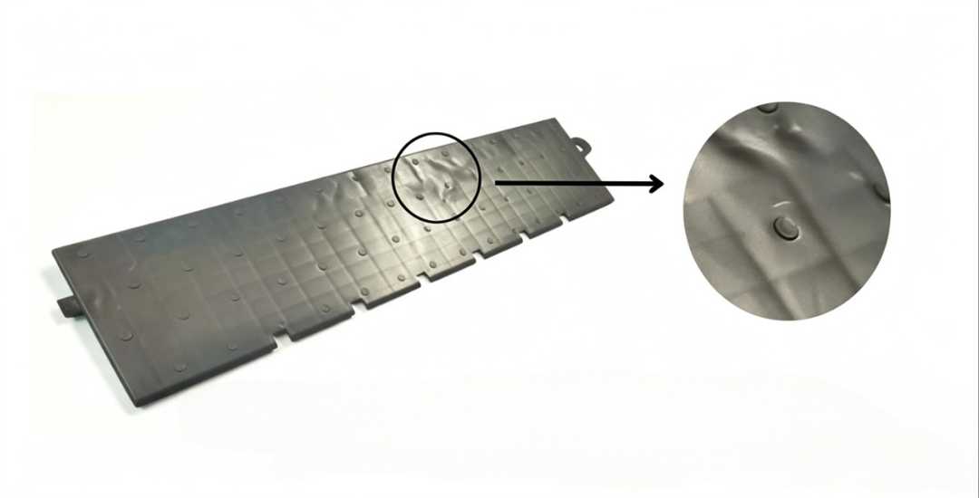
Sink marks are easier to correct when the defect is traced back to its location and likely cause instead of changing several molding parameters at once. A useful troubleshooting sequence starts with the part geometry and then moves through the mold, process, and material conditions.
Check Where the Sink Mark Appears
Compare the visible depression with the geometry on the opposite side of the wall. Sink marks that consistently appear above ribs, bosses, thick fillets, or intersecting features often indicate local material buildup and uneven cooling.
If the defect appears in the same location on every part, geometry, gate access, or local cooling should be reviewed before relying only on machine adjustments.
Review Packing and Gate Performance
Check whether packing pressure can still reach the affected region before the gate freezes. Sink marks that improve when holding pressure or holding time is adjusted may indicate insufficient shrinkage compensation.
Gate size, location, and flow path should also be reviewed if a thick section is difficult to pack consistently.
Check Cooling Balance
Compare the sink location with areas that remain hot longer during the cycle. Uneven mold temperature or limited cooling around a thick section can increase local shrinkage and make the defect more visible.
Cooling circuits, local hot spots, and actual cooling time should be checked together rather than adjusting cycle time alone.
Verify Material and Process Consistency
Confirm that the correct resin grade, filler content, drying condition, melt temperature, mold temperature, and validated process settings are being used. Changes in material condition or process stability can alter shrinkage and make a previously acceptable part develop sink marks.
If the defect remains after these checks, review part geometry, packing path, cooling balance, and material behavior together. Persistent sink marks usually require a root-cause correction rather than repeated small parameter changes.
6. How Mold and Process Conditions Affect Sink Marks
Part geometry strongly influences sink-mark risk, but mold design and molding conditions determine how well the process can compensate for shrinkage. Even a reasonable part design can develop sink marks if packing pressure cannot reach a thick section or if that area cools much more slowly than the surrounding material.
Gate Location and Size
The gate must remain connected to sink-prone regions long enough for packing pressure to compensate for volumetric shrinkage. If the gate freezes too early, additional melt can no longer enter the cavity even though thicker sections are still cooling and contracting.
Gate location, size, and the flow path therefore affect how effectively pressure reaches ribs, bosses, and other heavy sections. The goal is not simply to use a larger gate, but to maintain an effective packing path without creating unnecessary cycle-time or appearance problems.
Packing Pressure and Holding Time
Packing pressure supplies additional material after the cavity is filled, while holding time determines how long that compensation continues before the gate freezes.
Insufficient packing can leave thick sections under-compensated and increase sink depth. Increasing pressure or holding time may help, but excessive packing can introduce other problems such as residual stress or warpage. These settings should therefore be adjusted within a stable molding window rather than increased without limit.
Cooling Balance
Sink marks become more likely when one area of the part remains hot significantly longer than the surrounding wall. Cooling-channel layout and local heat concentration can therefore influence both sink severity and cycle consistency.
The objective is balanced heat removal around thick and sink-prone regions. When standard cooling channels cannot reach these areas effectively, local cooling solutions may be considered during mold design.
Melt and Mold Temperature
Melt and mold temperatures affect both material flow and the rate at which the part solidifies. Temperatures that are too high may extend cooling and increase shrinkage in thick sections, while temperatures that are too low can create filling or surface-quality problems.
For this reason, temperature should be maintained within the material’s validated processing range and adjusted together with packing and cooling conditions rather than treated as an isolated sink-mark setting.
Process changes can correct sink marks caused by inadequate packing, early gate freeze, or cooling imbalance. However, when the part contains a severe local thickness buildup, molding adjustments may only have limited room to compensate for the geometry.
Conclusion
Sink marks are rarely caused by one setting alone. Their location and severity usually reflect how part geometry, material shrinkage, packing, gating, and cooling interact during molding.
For this reason, the most effective approach is to identify the root cause before making repeated process adjustments. Design changes, mold improvements, and molding parameters each have a role, but the right solution depends on where the shrinkage is occurring and why.
For custom plastic parts, Beska can review 3D models, wall thickness, ribs, bosses, gate strategy, and other sink-risk areas before tooling, then support mold development, trial molding, and process verification through production.
 French
 English
 Hebrew
 Turkish
 Russian
 German
 Spanish
 Portuguese