


Grain direction is easy to overlook in tôle design because it is often less visible than bend radius, thickness, or tooling. Yet the rolling direction of the sheet can affect bendability, cracking tendency, springback, and surface appearance, especially when the material has strong directional properties.
The effect varies with alloy, temper, thickness, and forming conditions, so grain direction should not be treated as a universal “with-grain bad, cross-grain good” rule. This article explains how rolling direction affects pliage de tôles, which materials are more sensitive, how grain direction should be specified on drawings, and how it can be controlled during nesting and production.
1. What Is Grain Direction in Sheet Metal?
In sheet metal fabrication, grain direction usually refers to the rolling direction established during sheet production. As the sheet passes through rolling operations, its microstructure and crystallographic texture can develop directional characteristics, so the material may not behave exactly the same in every in-plane direction.
Rolling Direction and Material Anisotropy
The rolling direction follows the main direction in which the sheet is reduced and elongated during production. The direction perpendicular to it in the sheet plane is commonly called the transverse direction.
Differences in mechanical response between these directions are described as anisotropy. Depending on the alloy, temper, and processing history, properties such as ductility and formability can vary with orientation. This is why the same sheet can respond differently when a bend line is rotated relative to the rolling direction.
The plastic strain ratio, or r-value, is one parameter used to characterize anisotropy in sheet forming. It reflects how the material distributes plastic strain during deformation, but it is not a direct measure of bend-direction sensitivity.
Grain Direction vs Grain Size
Grain direction and grain size describe different features of the material structure. Grain direction relates to the orientation created by processing, while grain size refers to the dimensions of the individual grains within the microstructure.
The distinction becomes important when evaluating forming defects. Directional bend behavior is mainly associated with anisotropy and rolling orientation, while surface roughening such as orange peel is more closely linked to grain size and the amount of plastic deformation.
Metallurgical Grain vs Cosmetic Grain
In sheet metal work, the word “grain” is also used for visible directional finishes on brushed or sanded stainless steel and aluminum. These surface lines are created by the finishing process and are mainly controlled for appearance.
Cosmetic grain direction and metallurgical rolling direction are therefore separate requirements. A visible panel may need a consistent brushed direction for assembly appearance, while a formed part may need rolling direction controlled for bendability. In some components, both requirements have to be considered during blank layout and nesting.
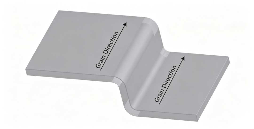
2. How Grain Direction Affects Sheet Metal Bending
Rolling direction can change how a sheet responds to bending because ductility and plastic deformation may vary with orientation. The effect is especially important when the bend radius is small, the material has limited forming margin, or several bends must be produced from the same blank.
Bend Orientation Relative to Rolling Direction
The important relationship is between the bend line and the rolling direction of the sheet. When the bend line is perpendicular to the rolling direction, the bend is commonly described as being across the grain. For many rolled sheet materials, this orientation provides better bendability than placing the bend line parallel to the rolling direction.
A bend line parallel to the rolling direction may require more forming allowance, particularly in materials or tempers with lower ductility. The difference is material-specific, so orientation should be checked together with the applicable bend data rather than treated as a universal rule.
Bend Radius and Cracking
Grain orientation can affect the minimum bend radius a material can tolerate without surface cracking. The effect becomes more noticeable as the bend becomes tighter and tensile strain increases on the outside of the bend.
There is no fixed radius correction that applies to every sheet. Alloy, temper, thickness, bend angle, edge condition, and rolling orientation all contribute to bendability. Where orientation-specific bend-radius data is available from the material supplier or forming standard, it provides a better basis than applying a general percentage increase.
Springback and Bend Consistency
Rolling direction can also contribute to differences in springback because the sheet may have direction-dependent strength and plastic behavior.
It is only one part of the result. Yield strength, temper, thickness, inside radius, tooling, and forming method also influence the final bend angle. If otherwise identical parts show different springback after the blank orientation changes, material anisotropy may be one of the causes to investigate.
Edge Condition and Bend Cracking
Bend performance is also affected by the condition of the cut edge. Sheared edges, laser-cut edges, burrs, and local edge damage can create sites where cracking starts during forming.
This becomes more important on tight bends or materials with limited ductility. Grain orientation and edge quality should therefore be considered together when a bend is close to the material’s forming limit, rather than assuming orientation alone determines whether cracking will occur.
3. Material Sensitivity and Surface Appearance
Grain direction does not affect every sheet material to the same extent. The response depends on the alloy, temper or material condition, thickness, and the processing history of the sheet.
Why Some Materials Are More Direction-Sensitive
Materials with limited ductility generally have less margin for tight bending, so differences between rolling orientations can become more noticeable. Higher-strength or hardened conditions often require more conservative bend geometry, while annealed or more ductile conditions usually tolerate forming more readily.
The effect still needs to be evaluated for the specific material. Alloy designation alone is not enough, because temper, thickness, heat treatment, and mill processing can all change bendability.
Cosmetic Grain Direction
Brushed, sanded, and other linear finishes create a visible surface grain that is separate from the metallurgical rolling direction.
For exposed panels, covers, and other cosmetic parts, this visual direction may need to remain consistent across adjacent components. In that case, the required finish direction should be shown on the drawing and preserved during blank nesting, even when rolling direction is not critical to forming.
Grain Size and Orange Peel
Orange peel is a surface-roughening effect that can appear when relatively coarse grains deform during bending or stretching. The surface develops a slightly pebbled texture as individual grains deform differently.
It should not be treated simply as a result of bending in the wrong grain direction. Grain size, material condition, and the amount of plastic strain are more direct contributors to this type of surface roughening.
4. How to Specify Grain Direction in Sheet Metal Design
Grain direction needs to be controlled only where it affects forming, function, or appearance. The drawing and flat pattern should make those requirements clear enough for nesting and fabrication without imposing unnecessary material restrictions.
Mark Rolling Direction When It Matters
When rolling direction is important, indicate it directly on the flat pattern with an arrow or drawing note. The requirement should identify which features or bend lines depend on that orientation rather than relying on the fabricator to infer it from the finished geometry.
Cosmetic finish direction should be identified separately if brushed or linear surface appearance also needs to be controlled.
Prioritize Critical Bends
A part with bends in several directions may not allow every bend to use the preferred orientation. In that case, tighter-radius bends, high-strain features, and bends with greater structural or cosmetic importance should receive priority during blank orientation.
Less critical bends may tolerate a less favorable orientation if the bend radius and material condition provide sufficient forming margin.
Use Material-Specific Bend Data
Minimum bend radius should be based on the actual alloy, temper, thickness, and bend orientation whenever reliable material data is available.
A fixed percentage increase for bends parallel to the rolling direction is not appropriate across different materials. Some grades show a clear directional difference, while others are much less sensitive.
Balance Grain Direction and Nesting Efficiency
Restricting grain direction reduces the number of ways parts can be nested on a sheet, which can increase scrap and material consumption.
For this reason, orientation requirements are most useful on features where they affect bendability or appearance. Parts with generous bend radii and no directional cosmetic requirement may allow more nesting flexibility.
Multi-Direction Bends
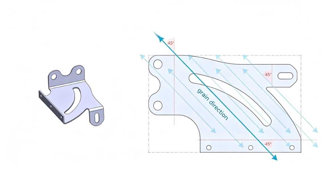
Complex brackets and enclosures often contain bend lines running in several directions, making one ideal blank orientation impossible.
The practical approach is to protect the most demanding bends first, then adjust bend radius, blank orientation, material condition, or temper where needed. A 45° blank orientation can sometimes balance directional behavior across several bends, but it should be validated for the specific material rather than treated as a general solution.
5. Production Verification and DFM
Grain-direction requirements need to remain traceable from raw sheet through nesting, cutting, and bending. For critical parts, verification should focus on preserving the specified orientation rather than trying to identify it after the blank has already been separated from the sheet.
Material Traceability
Mill markings, coil or sheet identification, supplier records, and internal material labels can be used to maintain the original rolling direction through production.
Once traceability is lost, surface appearance alone may not provide a reliable indication of rolling direction, especially on finished or processed sheet.
Nesting and Orientation Verification
When grain direction is specified on the drawing, the nesting layout should preserve that relationship before cutting begins.
This is particularly important when multiple parts are rotated to improve material utilization. A nesting change that improves sheet yield may also change the orientation of critical bends or cosmetic surfaces.
First Article Bend Inspection
First-article inspection can confirm whether the selected orientation and bend setup produce acceptable results before full production.
Critical bends should be checked for surface cracking, tearing, bend shape, springback, and any cosmetic change that affects the finished part.
Trial Bends When Needed
Trial bends can be useful for unfamiliar materials, new tempers, tight radii, or designs operating close to the expected forming limit.
They provide practical confirmation of bend behavior before production, but they are not necessary for every material lot or every sheet metal part.
Conclusion
Grain direction matters most when the material and forming condition are sensitive to orientation. Its effect can show up in bendability, cracking tendency, springback, or surface appearance, but the level of sensitivity varies by alloy, temper, thickness, and part geometry.
For this reason, rolling direction should be controlled where it has a clear functional or cosmetic purpose rather than specified automatically on every sheet metal part. Clear drawing requirements, practical nesting decisions, and first-article verification help keep grain-related risks under control without adding unnecessary manufacturing constraints.
For sheet metal parts with critical bend or appearance requirements, Beska can review grain direction, bend layout, and nesting strategy during DFM before production.
 French
 English
 Hebrew
 Turkish
 Russian
 German
 Spanish
 Portuguese