


Individual parts can meet their drawings and still be difficult to assemble. Hole position, mating fits, fastener access, surface condition, and tolerance stack-up only become fully visible when the components are brought together.
Mechanical assembly brings machined parts, sheet metal components, hardware, and other manufactured parts into a functional unit. The process may involve fastening, press fits, bonding, welding, or a combination of methods, depending on how the product needs to perform, be serviced, and be produced.
1. What Is Mechanical Assembly?
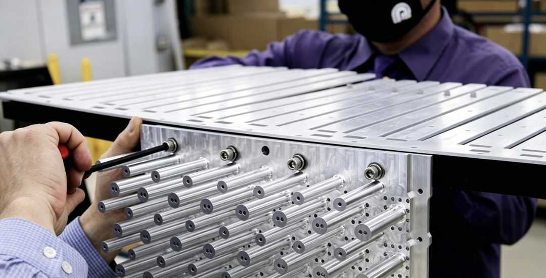
Mechanical assembly is the process of bringing two or more manufactured components together into a functional assembly or finished product. These components may include CNC-machined parts, sheet metal parts, cast components, fasteners, inserts, and other purchased hardware.
The process involves more than simply connecting parts. Components need to be positioned correctly, joined or secured using the appropriate method, and checked to confirm that the finished assembly meets its dimensional and functional requirements. For repeat production, the same assembly sequence also needs to produce consistent results from unit to unit.
The assembly method depends on factors such as load, material combination, required fit, access for tools, serviceability, production volume, and cost. Some products need removable fasteners, while others are better suited to press fits, bonding, welding, or a combination of methods.
2. Common Joining Methods Used in Mechanical Assembly
Mechanical assemblies can use several joining methods, depending on whether the connection needs to be removable, permanent, load-bearing, sealed, or easy to service. Mechanical fasteners, press fits, adhesive bonding, and welded or brazed joints are all common options.
Mechanical Fastening
Mechanical fastening uses screws, bolts, nuts, washers, rivets, inserts, and similar hardware to secure components. It is especially useful when parts need to be assembled predictably or removed later for maintenance.
For bolted joints, the required preload depends on the fastener, joint materials, surface condition, lubrication, and tightening method. Thread engagement and tool access also need to be considered during design. Rivets are more suitable for permanent joints, particularly in sheet metal assemblies where routine disassembly is not required.
Interference and Press Fits

A press fit uses controlled dimensional interference between mating parts to create a secure joint. Common examples include bearings installed in housings, gears mounted on shafts, and locating pins.
The required interference depends on the materials, diameter, wall thickness, load, surface condition, and operating temperature. Too much interference can overstress or deform the components, while too little may allow movement in service. ISO fit designations such as H7/p6 or H7/s6 can be useful starting points, but the final fit should be selected for the actual geometry and operating conditions.
Yapıştırıcı Bağlama
Adhesive bonding spreads load across a relatively large joint area and can be useful for joining dissimilar materials, sealing joints, or avoiding additional fastener holes.
Successful bonding depends heavily on surface preparation, adhesive selection, curing conditions, joint geometry, and the service environment. Temperature capability varies considerably between adhesive systems, so the manufacturer’s technical data should be checked for the actual load and exposure conditions. Bonded joints can also be difficult to disassemble without damaging the parts.
Welding, Brazing, and Soldering
Welding, brazing, and soldering are used when a permanent joint is required. Welding can produce strong structural connections, while brazing and soldering join components using filler metals without melting the base materials in the same way as fusion welding.
Heat input, material compatibility, distortion, joint access, and inspection requirements all influence process selection. Welded assemblies may also require fixturing or post-weld machining when dimensional accuracy around the joint is important.
3. Fits and Tolerances in Mechanical Assembly
Fits control of how mating features move, locate, or lock together after assembly. The required relationship between a hole and shaft is generally classified as a clearance, transition, or interference fit.
Clearance Fits
In a clearance fit, the smallest hole is still larger than the largest shaft, so clearance remains between the mating parts. These fits are used where sliding, rotation, easy assembly, or later disassembly is required.
ISO combinations such as H7/g6 or H7/h6 are common examples, but the actual clearance depends on the nominal size. Excessive clearance can create play or poor location, while insufficient clearance may cause binding under load or temperature change.
Interference Fits
In an interference fit, the shaft is larger than the mating hole within the specified tolerance limits. Assembly usually requires pressing or a controlled temperature difference between the parts.
Interference fits are commonly used for bearings, hubs, gears, and other joints where movement between mating surfaces needs to be restricted. The required interference depends on material properties, geometry, load, surface condition, and operating temperature.
Transition Fits
A transition fit falls between clearance and interference fits. Depending on the actual manufactured dimensions, the same tolerance combination may produce a small clearance or a light interference.
These fits are useful where accurate location is important but a heavy press fit is not required. Assembly force and removability depend on the actual size combination rather than the fit category alone.
ISO 286 and ANSI B4.1 provide standardized fit systems and tolerance classes, but the final choice should reflect the actual function of the assembly. Load, motion, temperature, service access, material combination, and manufacturing capability all influence the fit that works best in practice.
4. Design for Assembly (DFA) Principles
Design for Assembly focuses on making parts easier to handle, position, join, and inspect during production. Many assembly problems can be reduced early by simplifying the product structure and considering how each component will actually be installed.
Reduce Unnecessary Parts
Each additional component adds handling, inventory, and another assembly operation. Where the design allows, combining functions or reducing separate fasteners can simplify the assembly sequence.
Part reduction should still follow the product’s functional and service requirements. A removable component should not be integrated simply to reduce the part count if it needs to be replaced later.
Make Orientation Clear
Parts are easier to assemble when their orientation is obvious or when incorrect installation is physically difficult. Symmetry can sometimes remove the need for orientation, while asymmetric features can make the correct direction immediately clear.
Lead-ins, locating features, and clear mating geometry also help operators or automated equipment position parts without unnecessary adjustment.
Add Mistake-Proofing Features
Keyed features, unequal hole patterns, tabs, slots, and locating pins can prevent components from being installed in the wrong position or orientation.
These features are particularly useful when similar parts are assembled in the same product or when an assembly step would be difficult to inspect afterward.
Consider Automation Early
If automated assembly is planned, the part design needs to work with feeders, grippers, fixtures, sensors, and machine vision. Part presentation, access, orientation, and joining sequence can all affect whether automation is practical.
Designing around these requirements early is usually easier than modifying an assembly after the product geometry has already been fixed.
5. Manual vs. Automated Assembly
Manual and automated assembly suit different production conditions. The choice depends on part complexity, required throughput, product variation, labor content, and the level of investment needed for equipment and tooling.
Manual Assembly
Manual assembly works well when production volumes are relatively low, products change frequently, or certain steps still require operator judgment. Workers can handle irregular parts, make small adjustments during assembly, and switch between different products without major equipment changes.
Repeatability depends heavily on the assembly process itself. Clear work instructions, suitable fixtures, torque-controlled tools, and defined inspection steps help keep results consistent across different operators and production batches.
Automated Assembly
Automated assembly uses robots, feeders, fixtures, sensors, and dedicated tooling to perform repeated operations. It is most useful when the assembly sequence is stable and the same tasks are repeated at sufficient volume.
Automation can increase throughput and reduce variation in repetitive steps, but changes to the product may require new fixtures, programming, or tooling. Many production lines therefore combine both approaches, using automation for repetitive operations and manual assembly where flexibility or adjustment is still needed.
6. Common Assembly Problems and Their Causes
Assembly problems often appear when individually acceptable parts begin interacting with each other. Fit, alignment, fastener control, surface condition, and cleanliness can all affect the final result.
Misalignment
Misalignment can cause binding, uneven loading, difficult assembly, or poor motion between mating parts. Typical causes include tolerance stack-up, distorted components, inaccurate hole position, and insufficient locating features.
Dowel pins, pilot diameters, locating shoulders, and suitable fixtures can help control relative position where alignment is important.
Incorrect Fastener Tightening
Too much or too little fastener preload can affect joint performance. Excessive tightening may damage threads, distort softer components, or overload the fastener, while insufficient tightening can allow movement or loosening in service.
The required tightening method should account for the fastener, joint material, coating, lubrication, and specified preload. Torque-controlled tools can help maintain a consistent assembly process.
Surface and Thread Damage
Burred edges, damaged threads, scratched sealing faces, and handling marks can make assembly more difficult or affect the finished product.
Deburring, surface protection, correct handling, and suitable installation tools should be built into the assembly process rather than left for final inspection.
Chips, Dust, and Other Debris
Machining chips, dust, adhesive residue, and other debris can interfere with fits, moving parts, sealing surfaces, or electrical connections.
Components should therefore be cleaned and checked before final assembly, with additional cleanliness controls where the product or application requires them.
Çözüm
Good mechanical assembly starts before the parts reach the assembly bench. Fits, locating features, fastener access, surface condition, and tolerance stack-up all need to work together if the final product is expected to assemble smoothly and perform as intended.
Beska supports CNC işleme, sheet metal fabrication, and mechanical assembly within the same project. This makes it possible to review mating parts, hardware, and assembly requirements together rather than treating each component as an isolated part.
 Turkish
 English
 Hebrew
 French
 Russian
 German
 Spanish
 Portuguese