


Sheet metal parts can be cut and bent within tolerance and still be awkward to assemble. Panels may shift, holes may not line up cleanly, or operators may need extra clamps and repositioning before fastening or welding.
Tab-and-slot features are a simple way to control the relative position of mating parts before final joining. A tab on one component locates into a matching slot on the other, helping establish alignment and assembly direction.
The challenge is clearance. Too little can cause binding after cutting, bending, or coating, while too much reduces the locating accuracy that the feature was meant to provide.
1. What is Tab and Slot Design?
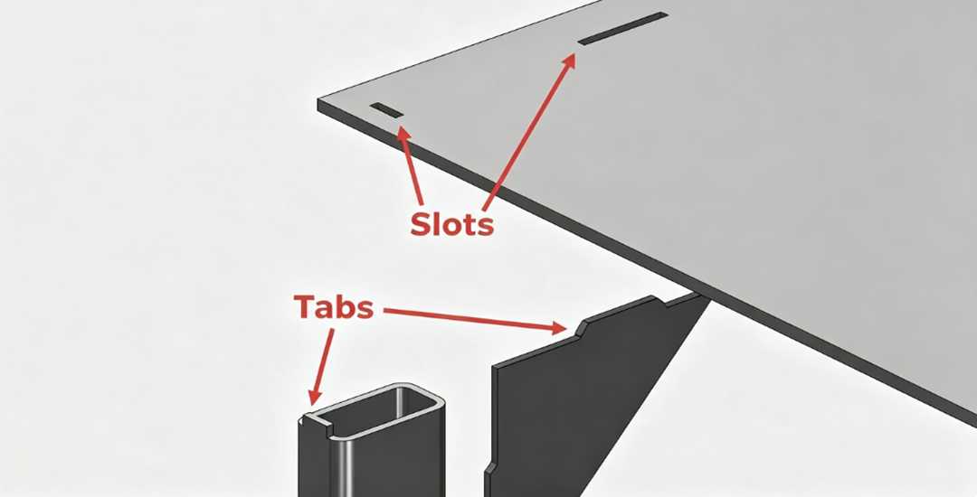
Tab-and-slot design uses matching features on two sheet metal parts to help locate them during assembly. One part includes a projecting tab, while the mating part has a slot that receives it and controls their relative position.
The feature is commonly used before fastening or welding because it can reduce manual measuring, repositioning, and fixture dependence. Tabs may also help control assembly direction or prevent unwanted movement, depending on their shape and placement.
The slot still needs enough clearance to accommodate normal cutting, forming, and finishing variation. If the fit is too tight, assembly becomes difficult; if it is too loose, the feature loses much of its locating value.
2. Key Dimensions in Tab and Slot Design
A tab-and-slot feature is defined by more than one dimension. Tab width, engagement length, slot size, edge distance, and the location of the feature all affect how the parts locate and assemble.
Tab Width and Engagement
Tab width affects both positioning and feature strength. Very narrow tabs are easier to deform and may provide limited guidance, while excessively wide tabs can make assembly more sensitive to dimensional variation.
Engagement length determines how far the tab enters the mating part. It should provide enough engagement to locate the parts without creating unnecessary interference with bends, fasteners, welds, or the assembly path.
Slot Size and Clearance
The slot must be larger than the finished tab by enough to accommodate material thickness variation, cutting tolerance, forming variation, and any coating on the mating surfaces.
There is no single clearance value that works for every sheet thickness or fabrication process. A laser-cut prototype, stamped production part, and powder-coated assembly may each require a different allowance.
Tab Location and Quantity
Tabs should be placed where they control the required movement without over-constraining the assembly. One locating feature may be sufficient when other edges or fasteners already control rotation, while more tabs may be useful on larger or less rigid parts.
Placement should also follow the assembly direction. A tab that interferes with a bend, fastener, weld access, or previously installed component can make an otherwise correct design difficult to assemble.
3. Typical Applications of Tab and Slot Features
Tab-and-slot features are commonly used where sheet metal parts need to locate relative to each other before fastening, welding, or final assembly.
Electronics Enclosures
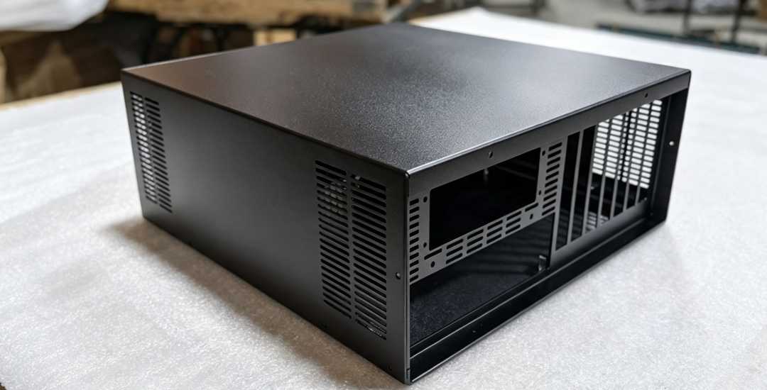
In electronics enclosures, tabs and slots can help position internal panels, covers, brackets, and mounting plates before screws or inserts are installed.
They are especially useful when several sheet metal parts must line up around common edges or mounting points, reducing the amount of manual repositioning needed during assembly.
Welded Frames and Brackets
Tabs and slots are also useful for welded sheet metal structures. They can locate brackets, gussets, and formed panels before tack welding, helping maintain the intended position while the joint is secured.
Fixtures may still be required for gap control, distortion, or final geometry, but locating features can reduce the amount of setup needed.
Other Sheet Metal Assemblies
The same principle is used in HVAC components, appliance housings, industrial control panels, cabinets, and other fabricated assemblies.
In each case, the purpose is similar: establish the relative position of the parts first, then complete the joint with fasteners, welding, or another joining method.
4. Manufacturing Considerations for Tab and Slot Features
Tabs and slots can be produced by corte por láser, punching, or stamping, depending on the material, part geometry, production volume, and required tolerance. The selected process affects feature size, edge condition, dimensional variation, and ultimately the clearance needed for assembly.
Cutting Process and Feature Capability
Laser cutting is well suited to prototypes and flexible production because it does not require dedicated cutting dies. Punching or stamping can become more efficient when production volume and part geometry justify dedicated tooling.
The achievable slot size and tolerance should be based on the actual material thickness and cutting process rather than a fixed design rule. Kerf, cut taper, machine capability, and feature geometry can all influence the finished opening.
Tolerance Stack and Part Variation
A tab and slot that fit correctly as individual features may still become difficult to assemble when several locating dimensions interact. Cutting tolerance, bend variation, hole position, and part flatness can all contribute to the final position of the mating features.
For multi-part assemblies, not every tab needs to act as a tight locating feature. Critical tabs can control position while other slots provide enough relief to absorb normal manufacturing variation without over-constraining the assembly.
Coating and Final Clearance
Plating, powder coating, and other additive finishes change the dimensions of both tabs and slots. A coated slot becomes smaller, while a coated tab becomes thicker, so the final assembly clearance can decrease from both sides.
Clearance should therefore be based on the specified coating process and expected coating thickness for the actual project. Masking may be a better option where a close-fitting feature cannot tolerate coating buildup.
First-Article and Production Control
Critical tab and slot dimensions should be checked during first-article inspection before the full batch proceeds. For coated parts, fit should be confirmed in the finished condition rather than only on bare metal.
In longer production runs, cutting or punching tools can gradually change feature dimensions or edge quality as they wear. Monitoring the dimensions that directly affect assembly helps identify drift before it becomes a fit problem.
5. Designing Tabs and Slots for Assembly
Tab placement should follow the way the parts will actually come together. Before adding tabs, define the assembly order, insertion direction, and access needed for fasteners, welding, or other joining operations.
Plan the Assembly Sequence First
A tab that works on the flat pattern may still interfere with another flange, bracket, or previously installed component during assembly. Tabs and slots should therefore be positioned around the actual movement of the parts rather than only around the final assembled geometry.
The design should also avoid forcing several tabs to locate the same part too tightly. One or two features may control position while other slots provide enough clearance to accommodate normal cutting and forming variation.
Check Access and Critical Features
Tabs should not block fastener holes, weld access, tooling, or inspection points. Lead-ins or asymmetric features can also be added where they help guide insertion or prevent incorrect orientation.
For production parts, critical tab and slot dimensions should be confirmed during first-article inspection, especially after bending or coating. If the required fit is close to the limits of the fabrication process, reviewing the design with the fabricator before release can prevent unnecessary rework later.
6. How to Specify Tab and Slot Features on a Drawing
A tab-and-slot design should give the fabricator enough information to control the features that actually affect assembly. Tab width, engagement length, slot size, and the location of critical features should be dimensioned clearly rather than left to interpretation from the CAD model alone.
Where the tab or slot controls part position, its location should be related to suitable datums or other functional features on the drawing. Not every slot needs the same tight positional tolerance; identifying the features that actually locate the assembly can avoid unnecessary machining or inspection requirements.
Finishing requirements also need to be clear. If powder coating, plating, or another additive finish affects the mating surfaces, the drawing should indicate whether the specified dimensions apply before or after finishing and whether any areas need masking. Assembly direction or other special notes are only necessary when the intended fit or installation sequence is not obvious from the geometry.
Conclusión
A good tab-and-slot design should locate the parts without making the assembly unnecessarily tight. Clearance needs to reflect the actual cutting, forming, and finishing process, while tab placement should follow the way the parts will be assembled.
For sheet metal projects, Beska can review tab and slot features together with laser cutting, bending, surface finishing, and final assembly requirements before production. This helps keep locating features practical to manufacture and consistent with the finished assembly.
 Spanish
 English
 Hebrew
 Turkish
 French
 Russian
 German
 Portuguese