


Carbon fiber reinforced polymer (CFRP) composites are increasingly used across industries for their outstanding mechanical properties and lightweight nature. From aerospace and transportation to consumer electronics and UAVs, this material offers strong structural potential.
This article walks through the key characteristics of carbon fiber composites, common applications, and machining techniques. It aims to help you assess whether this material fits your design and production needs.
1. What Is Carbon Fiber Composite?

CFRPs are engineered materials made by combining carbon fibers and a polymer resin matrix. The result is a material with a high strength-to-weight ratio, good dimensional stability, and excellent resistance to environmental factors.
| Componente | Propiedades | Función |
| Carbon Fiber (e.g., PAN-based) | Tensile strength up to 3000 MPa; fiber diameter ~5–7 μm | Main source of strength and stiffness |
| Resin Matrix (e.g., epoxy, phenolic) | Toughness, adhesion, low density, thermosetting | Binds fibers, transfers load, adds chemical resistance |
| Composite Behavior | Density: ~1.6 g/cm³; specific strength: 937–1875 MPa·cm³/g; near-zero thermal expansion | Enables lightweight, stable, high-performance structures |
This balance of components makes CFRP ideal for projects that require both mechanical performance and weight reduction.
2. Advantages of Carbon Fiber Composite

When a project demands high strength, light weight, and dimensional accuracy, carbon fiber composites offer several tangible advantages:
1. High Specific Strength and Stiffness
Compared to metals, CFRP delivers higher strength-to-weight performance.
| Material | Tensile Strength (MPa) | Densidad (g/cm³) | Specific Strength (MPa·cm³/g) |
| Aluminum Alloy | 500 | 2.7 | 185 |
| High-strength Steel | 1000 | 7.85 | 127 |
| Carbon Fiber Composite | 1500–3000 | 1.6 | 937–1875 |
This advantage is critical in applications where every gram matters.
2. Thermal Dimensional Stability
CFRPs exhibit very low coefficients of thermal expansion. Between −50°C and 150°C, their shape and size remain largely unaffected. This makes them suitable for applications with tight geometric tolerances, such as optical mounts or aerospace connectors.
3. Fatigue and Environmental Resistance
CFRPs maintain their mechanical integrity even after 100,000+ load cycles, typically retaining over 95% of initial strength. They also resist corrosion, making them suitable for humid or chemically aggressive environments without the need for metal coatings.
These benefits show why carbon fiber composites deserve early consideration in any high-performance design.
3. Common Processing Methods for Carbon Fiber Composites
Depending on part geometry, mechanical demands, and production volume, different processes offer distinct advantages. Here’s a quick comparison of the most commonly used processing methods:
| Método | Typical Use Cases | Pros | Considerations |
|---|---|---|---|
| Prepreg + Autoclave | Aerospace parts, UAV spars | High strength, low void content, precision | High tooling cost, slower cycle time |
| Resin Transfer Molding (RTM) | Drone shells, enclosures | Clean surface finish, mid-volume efficiency | Mold design is complex, moderate strength |
| Hand Lay-Up + Vacuum Bagging | Prototypes, large curved panels | Low tooling cost, flexible | Labor-intensive, lower consistency |
| CNC Cut Panels + Bonding | Frames, brackets, fixtures | Fast for flat parts, good repeatability | Not suitable for complex 3D shapes |
| Continuous Fiber 3D Printing | Custom jigs, light-duty parts | Rapid iteration, minimal setup | Limited strength, mostly for low-load designs |
For high-performance structural parts, autoclave curing offers the best results. For simpler forms or lower quantities, CNC cutting or hand lay-up may be more practical.
4. The Applications of Carbon Fiber Composite

CFRPs are no longer limited to aerospace or racing applications. Today, they are increasingly used across a wide range of sectors where high strength-to-weight ratio, fatigue resistance, and dimensional stability are critical. Typical examples include:
- Aerospace and UAVs: Structural spars, wing skins, fairings
- Consumer electronics: Lightweight device housings, internal frames
- Transportation: Panels, battery enclosures, seat frames
- Industrial equipment: Robotic arms, tool carriers, portable enclosures
These applications often place competing demands on the material—structural stiffness, crash resistance, manufacturability, or cycle time—making thoughtful process selection essential.
5. Cases of Carbon Fiber Composite
While carbon fiber composites are often associated with aerospace or racing industries, their real-world uses now span a much wider range. Whether you’re designing a lightweight structure, a ruggedized frame, or a precision component, CFRPs offer flexible solutions that go beyond conventional materials like aluminum or plastics.
To illustrate how this material is used in practice, here are two detailed manufacturing cases. Each one highlights how carbon fiber composites are tailored for specific performance goals.
Case 1: Consumer Drone Arm
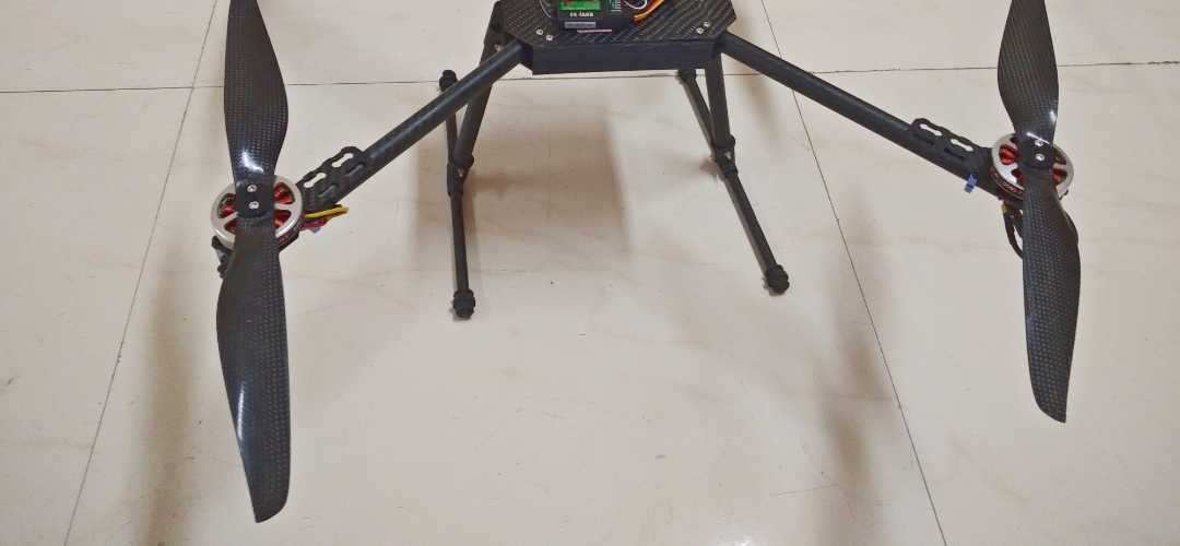
To meet the performance demands of compact quadcopters, a carbon fiber arm structure was developed that offered excellent torsional strength, low weight, and high production efficiency. The design had to support fast-moving rotors while enabling daily output of over 1000 units.
Material & Layup: A woven carbon fiber fabric was preformed to match the mold shape, achieving a 55% fiber volume fraction. The material was selected for its balance of strength and formability.
Forming Process: The arm was molded using Resin Transfer Molding (RTM). A low-viscosity epoxy resin (≤500 mPa·s) was injected under 0.4 MPa pressure into custom-designed flow channels. The entire cavity filled within 10 minutes. Curing was accelerated using microwave-assisted heating at 120°C for 1 hour.
Post-Processing: Thanks to precise mold design, most dimensions met final specs as-molded. Only minor edge trimming was needed, performed by CNC router systems.
Production Efficiency: This approach reduced per-part costs by approximately 40% compared to prepreg-based methods. Each mold tool supported large-scale output with minimal maintenance, making it ideal for cost-sensitive consumer markets.
With a final weight under 30 grams and torsional strength above 300 MPa, the resulting part met both structural and economic targets for mass-market aerial platforms.
Case 2: Performance Bike Frame

To improve ride efficiency and visual appeal, a high-performance bike frame was redesigned using carbon fiber composites. The goal was to reduce weight while maintaining structural stiffness and delivering a refined surface finish suitable for premium models.
Material & Layup: Straight tube sections were fabricated using filament winding at a 15° winding angle to enhance axial strength by over 60%. Curved joints and stress-concentration areas were reinforced with locally applied RTM to ensure consistent wall thickness and fiber placement.
Forming Process: After layup and consolidation, the cured parts underwent CNC milling to prepare key interfaces such as bottom bracket threads and disc brake mounts. Diamond tools running at 15,000 rpm ensured tight tolerance control (H7 fits, thread class 6H) and minimized fiber breakout.
Assembly & Finishing: Bonding areas were sanded and solvent-cleaned before applying structural epoxy adhesive. Final surface finishing included 800-grit sanding (Ra ≤ 0.8 μm) followed by a clear polyurethane topcoat (~50 μm thick) to enhance UV resistance and maintain the carbon weave appearance. High-end versions were further polished to a gloss level exceeding 90 GU.
Result: The complete frame weighed under 1.2 kg—approximately 40% lighter than its aluminum counterpart—while achieving improved stiffness and weather durability.
6. Machining Considerations and Technical Limitations
While CFRPs offer strong performance, they also require specific handling during fabrication and design. Below are common concerns and best practices:
Machining Guidelines
- Tooling: Use PCD or CBN tools to minimize delamination and edge burning. Standard carbide tools wear quickly.
- Dust Management: Carbon fiber dust is conductive and harmful. Equip workstations with vacuum extraction and isolate machines.
- Cutting Parameters: Limit the feed rate to 1000–1500 mm/min and depth of cut to <0.5 mm per pass to avoid fiber pull-out.
Fixturing: Combine vacuum hold-down and mechanical stops for large parts to prevent movement or deformation.
Design & Process Constraints
- Low Interlaminar Strength: Avoid single-point loading or bolt-through designs. Use local thickening and spread loads across surfaces.
- Tooling Cost: Autoclave or matched-die tooling is costly. For small batches, consider CNC trimming, RTM, or hand layup.
- Electrical Conductivity: CFRPs conduct electricity. Add insulation layers when used in contact with electrical components.
Considering these factors early can greatly reduce scrap rates and ensure the full benefits of CFRPs are realized.
Conclusión
CFRP is a compelling choice when structural strength, weight savings, and long-term performance are priorities. It’s no longer limited to niche sectors—its value is clear in everyday engineered components, especially when optimized for the application.
With appropriate design and processing strategies, carbon fiber composites can replace metal or plastic in many CNC-machined parts, molded structures, or precision assemblies. Looking for an expert for custom manufacturing solutions? Contacto the Beska team. We’d like to turn your drawings into high-quality carbon fiber parts.
Profundice en nuestros recursos
¿Busca más opciones de servicio? Explore nuestra selección cuidadosamente seleccionada:
Para que disfrutes de lecturas interesantes, hemos preparado una lista de artículos recomendados solo para ti:
 Spanish
 English
 Hebrew
 Turkish
 French
 Russian
 German
 Portuguese