


Fatigue and creep are two failure mechanisms that engineers often confuse. Both occur under stress and can eventually cause component failure, but they develop under very different operating conditions and require different engineering solutions.
Confusing fatigue with creep can lead to selecting the wrong material, applying the wrong design strategy, or investigating the wrong failure mechanism. In practice, these mistakes often result in unnecessary redesigns, shortened service life, or unexpected component failure.
This article explains how fatigue and creep develop, how to distinguish them during failure analysis, and how engineers choose appropriate materials and design strategies for different operating conditions.
1. What is Fatigue?
Components subjected to repeated loading do not always fail immediately. Even when the applied stress remains below the material’s yield strength, microscopic damage can gradually accumulate over thousands or even millions of load cycles until the remaining section suddenly fractures. This failure mechanism is known as fatigue.
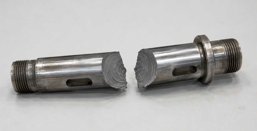
Fatigue almost always begins at a local stress concentration. In CNC-machined components, common crack initiation sites include machining marks, sharp internal corners, tooling-induced surface defects, and weld toes. Once a crack forms, it extends slightly with each load cycle until the remaining cross-section can no longer support the applied load, resulting in sudden fracture with little or no visible warning.
One of the most recognizable features of fatigue is the fractured surface. Beach marks or microscopic striations reveal how the crack propagated over time before final failure. During design, engineers use S-N curves to estimate fatigue life under different stress levels and establish safe operating limits for cyclic loading.
Fatigue commonly affects rotating shafts, gears, springs, welded joints, and pressure vessels exposed to repeated loading. Any component subjected to cyclic stress should be evaluated for fatigue during the design stage, even when the applied stress never exceeds the material’s yield strength.
2. What is Creep?
Creep occurs when a component operates under constant stress at elevated temperature for an extended period. Even when the applied stress remains below the material’s yield strength, the material can slowly deform over time. If this deformation continues to accumulate, the component may eventually lose its dimensional accuracy or fracture.
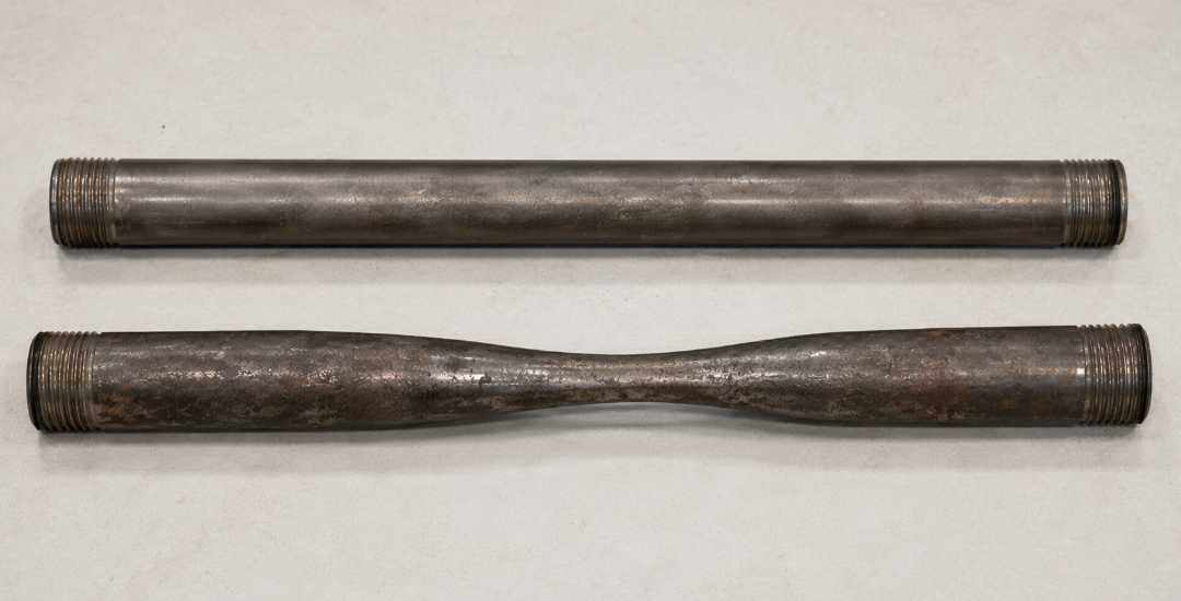
The deformation develops gradually through three stages. During primary creep, the deformation rate is relatively high before slowing down. Secondary creep follows with a stable and predictable deformation rate, making it the basis for most creep life calculations. As damage accumulates, tertiary creep begins, and the deformation rate increases rapidly until failure occurs.
Unlike fatigue, creep usually provides visible warning before fracture. Components often show stretching, thinning, or permanent deformation long before they fail, allowing inspection and replacement before catastrophic failure. Fracture surfaces typically contain grain boundary cavities and voids, reflecting the progressive nature of high-temperature damage.
Creep is commonly found in turbine blades, boiler tubes, steam piping, exhaust manifolds, heat exchangers, furnace tubing, and other components operating above approximately 0.4 times the material’s melting temperature (Tm). Any component exposed to high temperature under sustained load should be evaluated for creep during the design stage.
3. Key Differences: Fatigue vs Creep
Fatigue and creep are often confused because both involve stress and can eventually lead to component failure. However, they are fundamentally different failure mechanisms that require different engineering approaches.
Aspecto | Fatigue | Creep |
|---|---|---|
Driving load | Cyclic or alternating stress | Constant stress |
Temperatura | Any temperature (room or low) | High (usually above 0.4 Tm) |
Warning signs | None, sudden fracture | Visible deformation before failure |
Fracture surface | Beach marks, striations | Grain boundary cavities |
Time dependence | Cycle-dependent | Time-dependent |
Design focus | Avoid stress concentrations, smooth surfaces | Control temperature, select heat-resistant materials |
For steel, creep typically becomes a design concern above approximately 350°C, while for aluminum it may begin around 150°C. Actual thresholds vary depending on material grade, heat treatment, operating stress, and service conditions.
In practice, the distinction is straightforward. Components subjected to repeated cyclic loading require fatigue analysis, while components operating under sustained loads at elevated temperature require creep analysis. Where both conditions exist, such as turbine blades, gas turbine discs, and other high-temperature rotating equipment, fatigue and creep should be evaluated together during design and life prediction.
Sources: ASM International; ASTM E606/E139 standards; published fatigue and creep data from material suppliers.
Note: Values shown are typical industry ranges. Actual thresholds vary depending on material grade, heat treatment, loading conditions, and test environment. Temperature values are approximate and should be verified for specific materials and operating conditions.
4. Fatigue-Creep Interaction
Some components operate under both elevated temperature and repeated cyclic loading. Turbine blades, gas turbine discs, and boiler tubes are common examples. In these applications, fatigue and creep do not act independently but interact with each other, making failure prediction more complex than considering either mechanism alone.
When both mechanisms are present, damage caused by one accelerates the other. Creep weakens grain boundaries, making it easier for fatigue cracks to initiate and propagate. At the same time, fatigue cracks create local stress concentrations that accelerate creep deformation around the crack tip. As damage accumulates, the combined effect shortens component life much faster than either fatigue or creep acting alone.
Designing for these conditions requires evaluating both mechanisms together. Engineers use creep-fatigue interaction models and cumulative damage rules to estimate service life under combined loading. For critical high-temperature components, considering fatigue or creep alone is rarely sufficient for reliable design and life prediction.
5. Failure Analysis: How to Tell Which One Caused the Failure
When a component fails, distinguishing between fatigue and creep starts with four observations: operating temperature, fracture surface, visible deformation, and service history. Together, these provide the evidence needed to identify the dominant failure mechanism.
Check | Fatigue | Creep |
|---|---|---|
Temperatura | Any temperature | High (above 0.4 Tm) |
Fracture surface | Beach marks, striations | Grain boundary cavities |
Deformation before failure | Little or none | Visible stretching, thinning |
Service history | Cycle-dependent | Time-dependent |
Temperature is usually the quickest filter. If the component operated at relatively low temperature, creep is unlikely. The fracture surface then provides the strongest evidence, while visible deformation and service history help confirm the diagnosis. Evaluating these four observations together usually narrows the failure mechanism quickly and reliably.
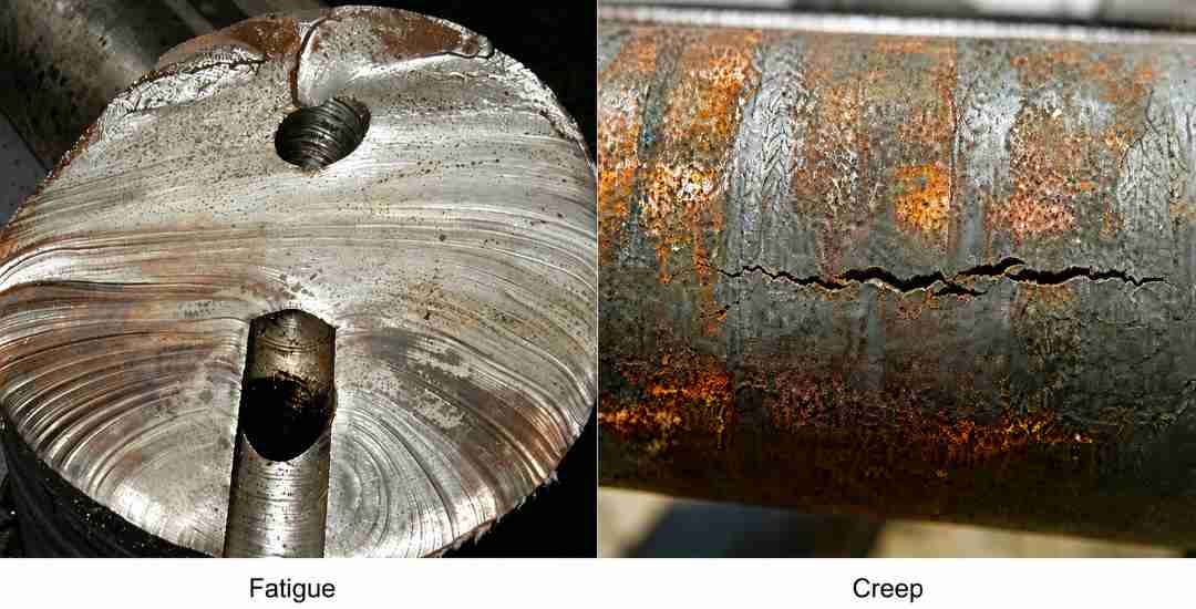
This approach is sufficient for most common engineering failures. When the evidence is inconclusive or multiple failure mechanisms may be be involved, additional techniques such as metallographic examination, scanning electron microscopy (SEM), microhardness profiling, and macrofractography can be used to verify the root cause.
Sources: ASM International; ASTM E606/E139 standards; published failure analysis guides.
Note: Values shown are typical industry ranges. Actual thresholds vary depending on material grade, heat treatment, loading conditions, and specific operating conditions.
6. Design Strategies for Fatigue vs Creep Resistance
The design approach depends on the component’s operating conditions. Repeated cyclic loading requires fatigue resistance, while sustained loading at elevated temperature requires creep resistance. Some applications must be designed to withstand both.
Improving Fatigue Resistance
Fatigue cracks usually initiate at the surface, making stress concentration and surface quality the primary design considerations. Generous fillet radii, smooth surface finishes, and gradual geometry transitions help reduce local stress concentrations. Surface treatments such as shot peening, nitriding, and carburizing further improve fatigue life by delaying crack initiation.
Manufacturing quality also has a direct influence on fatigue performance. Controlling machined surface finish, minimizing residual stresses from machining or grinding, ensuring consistent weld quality, and removing burrs all help reduce potential crack initiation sites and extend component life.
Improving Creep Resistance
Creep resistance depends largely on a material’s ability to retain strength during long-term exposure to elevated temperature. Material selection is therefore the primary consideration. Alloys such as Inconel 718 for turbine discs, Hastelloy X for combustion liners, and P91 steel for high-temperature steam piping are widely used because they maintain their mechanical properties under sustained thermal loading.
Operating temperature and applied stress are equally important. Lower temperatures, reduced stress levels, and designs that allow periodic inspection all help delay creep deformation. In applications where high temperatures cannot be avoided, protective coatings and internal cooling features are commonly used to extend service life.
Balancing Fatigue and Creep
Materials that perform well against fatigue are not always the best choice for creep. High-strength alloys provide excellent fatigue resistance at moderate temperatures but often lose strength as temperature increases. Heat-resistant alloys maintain their properties at elevated temperatures, although they may offer lower fatigue performance and higher material cost.
The priority should always follow the operating conditions. Rotating shafts, gears, and other room-temperature cyclic components are typically designed with fatigue resistance in mind. Turbine blades, boiler tubes, and other high-temperature components prioritize creep resistance. Where cyclic loading and elevated temperature occur together, material selection, cooling strategy, protective coatings, and life prediction should be considered together to achieve the required service life.
7. Common Misconceptions About Fatigue and Creep
Misconceptions about fatigue and creep are common in engineering and can lead to incorrect material selection, unsuitable design decisions, or ineffective failure analysis. The following are some of the most common examples.
Fatigue Only Happens in Steel
Fatigue is not limited to steel. Aluminum, titanium, copper, and their alloys can all fail under repeated cyclic loading. In every case, fatigue begins with a crack at a local stress concentration, which gradually grows until the remaining section can no longer support the load. Plastics, ceramics, and composite materials can also experience fatigue, although the failure behavior differs from that of metals.
Creep Only Happens at Very High Temperatures
High temperature is relative to the material rather than a fixed value. Aluminum begins to creep at much lower temperatures than steel, while lead can creep under its own weight at room temperature. For many engineering alloys, creep becomes a design concern above approximately 0.4 times the material’s melting temperature (Tm), although the actual threshold depends on the material grade and operating conditions.
Fatigue Is Always a Slow Failure
Fatigue damage develops gradually, but fracture often occurs suddenly. Crack initiation may require thousands or even millions of load cycles, yet once the crack reaches a critical size, failure can occur with little or no visible warning. The gradual part of the process is usually hidden until the final fracture.
Visible Deformation Means Creep Is Not Dangerous
Visible deformation is a warning, but it does not guarantee there is still time to intervene. In many high-temperature applications, even a small amount of creep deformation can cause loss of alignment, interference between moving parts, or unacceptable dimensional changes before fracture occurs. Any measurable creep deformation should be treated as an indication that the component requires further evaluation.
Creep Only Matters in Long-Term Service
Service time alone does not determine whether creep is a concern. The creep rate depends on the combined effect of temperature, applied stress, and material properties. Components operating under extreme conditions may experience significant creep within hours, while others remain stable for years under lower temperatures and stresses.
Each misconception leads to the same outcome: the wrong failure mechanism is identified, and the wrong engineering solution follows. Material selection, design improvements, and maintenance planning should always be based on the actual operating conditions rather than assumptions about how fatigue or creep behaves.
Conclusión
Fatigue and creep require different engineering decisions because they occur under different operating conditions. Components subjected to repeated cyclic loading should be evaluated for fatigue, while components operating under sustained loads at elevated temperature should be evaluated for creep. When both conditions exist, material selection, component design, and life prediction should consider both mechanisms together to achieve reliable long-term performance.
At Beska, we manufacture precision CNC machined components for demanding engineering applications where fatigue and creep performance are influenced by material selection, heat treatment, machining quality, and surface condition. During DFM review, we evaluate these factors together to help customers reduce manufacturing risks, improve component reliability, and achieve consistent performance from prototype through production.
Deeper into Our Resources
Para que disfrutes de lecturas interesantes, hemos preparado una lista de artículos recomendados solo para ti:
 Spanish
 English
 Hebrew
 Turkish
 French
 Russian
 German
 Portuguese