


In the world of sheet metal design and fabrication, the bend radius may seem like a minor detail, but it can make or break a part. It serves as the bridge between creative design and manufacturability and is a key indicator of an engineer’s understanding of materials and processes. Ignoring it can lead to scrap, increased costs, and production delays, while mastering it allows you to design parts that balance aesthetics, strength, and cost-efficiency.
This guide takes you through the fundamentals of sheet metal bend radius, explores the factors that affect it, and provides practical tables and formulas to help you achieve precise, manufacturable designs.
1. Definition and Classification of Sheet Metal Bend Radius

The bend radius refers to the radius of the inner arc formed when sheet metal is bent. The outer bend radius is typically the inner radius plus the material thickness (R_outer = R_inner + t). In engineering drawings, the inner radius (R) is the standard reference, ensuring clear communication with manufacturers.
Bend radii can be categorized as
- Minimum Bend Radius: The smallest radius at which the material can bend without cracking, determined by material ductility and thickness.
- Recommended Bend Radius: The optimal radius balancing manufacturability, cost, and strength, usually slightly larger than the minimum.
- Custom Bend Radius: Special radii designed for appearance or assembly requirements, verified through process testing.
- Physical Basis: Bending involves plastic deformation, with the outer fibers in tension and inner fibers in compression. The bend radius directly influences the strain on the outer fibers and therefore part integrity.
The bend radius sets the foundation for reliable and efficient bending, influencing both part performance and manufacturability.
2. Key Process Parameters of Bending Radius
The bend radius does not exist in isolation. It must be considered along with material thickness, bend angle, and bending force.
| פָּרָמֶטֶר | Influence | Example (Q235 Cold-Rolled Steel) |
| Material thickness (t) | Thicker sheets require larger minimum bend radii to prevent cracking | t = 1 mm → R_min ≈ 0.5mm; t = 10mm → R_min ≈ 5mm |
| Bend angle (θ) | Sharper bends (smaller angles) increase stress concentration, requiring larger radii | θ = 90° → R_min = 0.5–1t; θ = 60° → R_min ≥ t |
| Bending force (F) | Smaller radii require greater force for plastic deformation | R = 0.5t requires ~30% more force than R = t |
Achieving a consistent bend requires more than just following numbers. Material, angle, and force interact in ways that affect springback, tool wear, and part quality, so experienced engineers always plan for these factors during design and setup.
3. The Importance of Bend Radius
The bend radius influences almost every aspect of a part, from structural performance to its final appearance. It is far more than just the size of a corner.
- Structural integrity: A too-small bend radius can overstretch the outer fibers, leading to micro-cracks or part failure, which reduces fatigue life. Choosing the right radius preserves material strength and ensures reliability.
- Dimensional accuracy: Over-stretched material may distort, making it difficult to maintain tight tolerances. A properly selected radius allows predictable springback and precise final dimensions.
- Manufacturability: Extremely small radii may require special tooling or even be impossible to bend, increasing scrap and production costs. Using an appropriate radius enables standard tooling and smoother operations.
- Appearance and safety: Sharp corners are prone to scratches, look harsh, and may pose safety risks. Rounded bends create a more polished look and reduce the risk of injury.
- Post-processing: Coating, plating, or painting can be uneven around tight corners, leading to poor adhesion and premature wear. Correct radii ensure a uniform surface finish and better durability.
The bend radius is a subtle yet critical design element. A carefully chosen radius not only strengthens the part but also improves manufacturability, appearance, and surface quality, making it a cornerstone of practical and reliable sheet metal design.
4. Factors Affecting Bend Radius Selection


The bend radius is determined by a combination of material properties, part design, tooling and equipment, and process considerations. Each of these factors interacts, and small adjustments in one can significantly affect the others.
מאפיינים חומריים
- Ductility (elongation): More ductile materials allow smaller bend radii. Soft aluminum, for example, can be bent tighter than low-carbon steel or stainless steel.
- Material thickness (t): Thicker sheets experience higher strain on the outer fibers, requiring proportionally larger radii. Designers often use the R/t ratio as a guideline, with sheets thicker than 3mm needing larger ratios.
- Grain direction: Bending parallel to the material grain increases the risk of cracking along brittle boundaries. Whenever possible, bends should be perpendicular to the grain, or the radius should be increased by 1.5–2 times.
- Strength/hardness: High-strength or hard materials resist plastic deformation and show significant springback, so engineers plan larger radii and account for springback compensation.
Part Design Requirements
- Structural strength: Load-bearing parts may require the inner radii of 2t–3t to improve section inertia, while non-structural parts can use smaller radii.
- Appearance: Visible components, such as appliance panels, benefit from R_inner ≥ 1.5t to ensure smooth transitions.
- Assembly: Clearance for fasteners or mating parts is crucial. For example, an M5 bolt requires R_inner ≥ 5.2mm.
Equipment and Tooling
- Press brakes: Machines with limited tonnage cannot achieve very small radii. CNC press brakes offer higher precision with ±0.02mm repeatability.
- Tooling: The punch and die geometry determine the achievable bend radius. Tool wear exceeding 0.1mm requires replacement or repair to maintain accuracy.
Process Considerations
- Air bending: Radius depends on die opening and material properties, providing flexibility for most 90° or non-90° bends.
- Bottoming: Punch tip directly determines the radius, ensuring high precision and reduced springback.
- Coining: Fully shapes the material, minimizing springback and achieving sharp edges, commonly used for high-strength parts or where smooth corners are critical.
Choosing the right bend radius requires balancing material behavior, part function, tooling limitations, and process characteristics. Successful designs account for all these factors, ensuring parts are manufacturable, durable, and visually consistent.
5. Calculating Sheet Metal Bend Radius
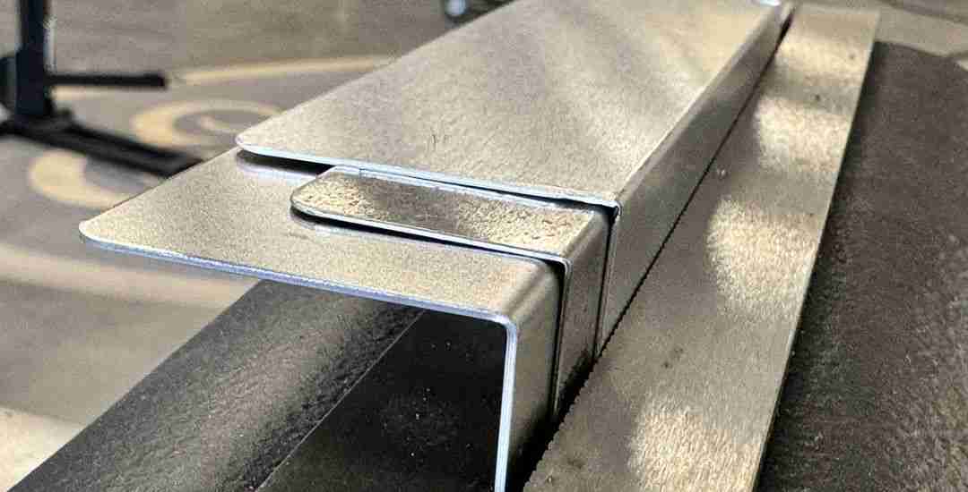
The appropriate bend radius depends largely on the material, as factors such as ductility, hardness, and springback vary between metals. Selecting the right radius ensures reliable bends, prevents cracking, and maintains part quality.
5.1 Recommended Bend Radius by Material
| חוֹמֶר | Example Grade | Recommended R_inner | Minimum R_inner | הערות |
| Low-carbon steel | Q235, SPCC | 0.5–1t | 0.4t | High ductility, wide process window |
| Stainless steel | 304, 316 | 0.5–1t | 0.5–1t | High springback; state (2B, BA) affects radius |
| Soft aluminum | 1060, 1100 | 0.5–1t | 0.4t | Easy to bend, avoid surface marks |
| Medium-hard aluminum | 5052-H32 | 1–1.5t | 0.8t | Balanced strength and formability |
| Hard aluminum | 6061-T6 | 2–3t | 1.5t | High risk of cracking; bending after solution treatment recommended |
| פְּלִיז | C2600 | 0.8–1.5t | 0.6t | Sensitive to grain direction |
| נְחוֹשֶׁת | C1100 | 0.5–1t | 0.4t | Very ductile but soft; watch for tool marks |
Golden Rule: Unless otherwise required, set R_inner = t. This provides a good balance of performance, appearance, and cost in ~90% of cases.
5.2 Springback Compensation
After bending, parts may recover elastically, causing R_actual > R_tool. Compensation is done by adjusting tooling or bending angle.
| חוֹמֶר | K-factor range | הערות |
| Carbon steel | 0.8–1.0 | Sheet ≤5mm cold-rolled; thicker sheets use upper limit |
| Stainless steel | 1.2–1.5 | Cold-rolled, unannealed; annealed reduces to 1.0–1.2 |
| אלומיניום 5052 | 1.0–1.2 | Soft (O) ≤3mm; H32 1.2–1.3 |
| אלומיניום 6061 | 1.3–1.5 | T6 ≤4mm; O state 1.0–1.1 |
5.3 Unfolded Length Calculation
Based on the neutral axis theory:
L = Sum of straight edges + Neutral layer arc length
| R_inner / t | Neutral axis offset x | Example Material |
| ≥2t | ~0.5t | All ductile materials |
| t–2t | ~0.45t | Carbon steel, stainless steel |
| ≤ t | ~t/3 | Carbon steel, aluminum |
Example: Q235 steel, t = 2 mm, R_inner = 1 mm, L1 = 50mm, L2 = 30mm, θ = 90°
Neutral arc length ≈ 2.62mm → Unfolded length L ≈ 82.62mm (rounded to 82.7mm).
6. Optimizing Sheet Metal Bend Radius for Manufacturability
Selecting the right bend radius is not just about meeting design specifications—it directly affects production efficiency, cost, and downstream processes. Keeping manufacturability in mind early helps prevent common issues during fabrication.
- Communicate with your supplier: Discuss bend radii before finalizing designs—they can advise on feasible ranges.
- Standardize radii: Use consistent radii across parts to reduce tooling changes and minimize costs.
- Design for post-processing: Choosing radii ≥ material thickness ensures better coating or plating quality.
- Leverage CAD/DFM tools: Analyze manufacturability and detect potential issues early.
Early consideration of bend radius from both design and production perspectives ensures parts are easier to manufacture, more reliable, and meet quality expectations—saving time and reducing costs in the long run.
מַסְקָנָה
The bend radius, a small detail hidden in every corner, encapsulates the essence of sheet metal design. It tests a designer’s understanding of materials, processes, and the art of balancing constraints to achieve optimal solutions.
Using this guide and its tables as a reference moves you from “can draw it” to “can produce it reliably and efficiently.” Excellence in sheet metal design comes from understanding and respecting every detail.
When planning your next project, consult an experienced sheet metal forming partner like the Beska team, who can ensure your chosen bend radii are feasible, optimized for manufacturing, and aligned with quality and cost targets.
צלול עמוק יותר לתוך המשאבים שלנו
לקריאה מעמיקה, אספנו עבורך רשימה של מאמרים מומלצים:
- 9 שלבים כיצד לכופף גיליון מתכת
- How to Weld Stainless Steel
- Sheet Metal Forming Service
- Sheet Metal Bending Service
 Hebrew
 English
 Turkish
 French
 Russian
 German
 Spanish
 Portuguese