


An engineer sends a PEEK part drawing to three shops. The drawing calls for a 20 mm bore at ±0.01 mm. Shop A says no problem. Shop B says ±0.025 mm is the best they can do. Shop C says they need to anneal twice and the price doubles. All three are telling the truth, because PEEK does not have one tolerance. It has a tolerance range that shifts with geometry, material grade, and process sequence.
Getting PEEK tolerances wrong hurts more than other plastics. A scrapped acetal part costs a few dollars. A scrapped PEEK part costs 8 to 12 times more in material alone. In semiconductor or medical applications, the cost includes line downtime and regulatory delays.
In this article, you will learn realistic tolerance levels across לְהָצִיץ grades and feature types, how annealing changes what you can hold, and the process decisions that separate prototype from production repeatability.
1. What Is PEEK Machining Tolerance?
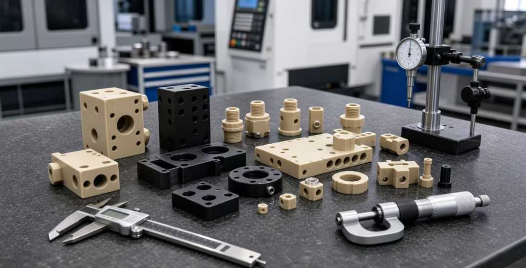
PEEK machining tolerance is the dimensional deviation a CNC process can reliably hold on PEEK parts under production conditions. Unlike metals where tolerance is largely a machine tool specification, PEEK tolerance is a system outcome shaped by four interacting variables:
- Material grade. Unfilled, GF30, and CF30 respond differently to cutting heat, tool wear, and stress relief, so the same feature holds different tolerances across grades.
- Feature geometry. A 20 mm through-bore behaves differently from a 3 mm blind pocket, even on the same part and fixture.
- Stress history. Extruded stock carries residual stress that is not uniform across the cross-section. Where the part came from in the billet matters.
- Thermal conditions. PEEK expands roughly 47 to 55 µm/m/°C, so measurement temperature alone can move a dimension by more than the tolerance band.
These four variables do not add linearly. A stress-relieved unfilled PEEK bore at 1:1 depth ratio holds ±0.02 mm with routine process control. The same part with a 5:1 blind pocket in CF30 cut from unstress-relieved stock at an uncontrolled shop temperature will not hold ±0.1 mm. Understanding which variable dominates on each feature is what separates repeatable production from first-article luck.
2. Unfilled vs GF30 vs CF30: Tolerance by Grade
The three grades serve different functions, and their tolerance behavior follows no single ranking. A grade that holds OD well may struggle with small holes. Understanding these trade-offs before selecting a grade avoids the cost of remaking the same part in a different material. The comparison below covers tolerance behavior across the key performance dimensions.
- Unfilled as the default. Unfilled PEEK holds ±0.05 mm with a single anneal on walls above 6 mm. Tightening to ±0.025 mm requires rough-anneal-finish, temperature control, and disciplined measurement. Below ±0.01 mm adds a second anneal; each step roughly doubles process cost.
- Filled grades flip by feature type. On external diameters, GF30 and CF30 hold tighter than unfilled because lower CTE reduces thermal growth during cutting. On small holes under roughly 3 mm, the opposite is true: glass and carbon fibers abrade the cutting edge unevenly. Unfilled PEEK typically produces less diameter variation on these features. For flatness over 25 mm, CF30 is the best performer due to its stiffness, followed by GF30, then unfilled.
- Tool life drops with filler content. Unfilled PEEK on sharp polished carbide is the most forgiving combination and the lowest cost. GF30 cuts tool life by half to two-thirds because glass fibers are abrasive. CF30 is the most abrasive, making tool condition the dominant variable and pushing PCD tooling into the economic equation at moderate volumes.
- Cost follows tool life and scrap risk. Unfilled is the lowest material cost and the easiest to rework. GF30 costs more for stock and tooling, and a scrapped GF30 part wastes both because you cannot recover the tooling cost. CF30 is the most expensive combination, reserved for applications where stiffness, wear resistance, or electrostatic dissipation justify the machining difficulty.
Grade property data referenced from Victrex PEEK technical datasheets, Ensinger TECAPEEK product specifications, and internal Beska process records for machined PEEK components.
Choose grade on service requirements first, then design the process around that grade’s tolerance behavior.
3. How Annealing, Heat, and Measurement Affect PEEK Tolerances
Grade sets the baseline. Three factors then determine inspection results.
PEEK’s Tg around 143°C means the cutting zone easily softens the material in deep pockets, degrading chip evacuation and dimensional control. Stock stress adds a hidden variable: extruded rod and plate carry residual stress that is not uniform across the cross-section. At Beska, parts from the center of a large-diameter rod hold tighter dimensions than parts cut from the outer third, because the stress profile is more balanced in the core.
Annealing: When One Cycle Is Not Enough
Annealing relaxes internal stresses before finish machining. A typical cycle for unfilled PEEK runs 3 to 4 hours at 150 to 200°C with ramping around 10 to 15°C per hour. For precision work, rough machine to 0.5 to 1.0 mm of final, anneal, then finish. Through-holes and symmetric diameters respond well to one anneal; deep blind pockets and thin-walled bosses need the two-step sequence. At Beska, flatness tighter than 0.05 mm per 25 mm on walls under 4 mm defaults to rough-anneal-finish.
Heat Management During Cutting
PEEK traps heat at the cut zone because its thermal conductivity is roughly 800 times lower than aluminum, so dry compressed air is standard for unfilled grades. Flood coolant risks thermal shock micro-cracking. Filled grades tolerate light mist coolant for chip evacuation without the thermal shock. High surface speed with low chip load pushes heat into the chip rather than the part.
Measurement: Temperature Changes the Number
A 6°C ambient shift changes a 50 mm feature by roughly 0.014 to 0.017 mm, larger than most precision tolerance bands. Features tighter than ±0.03 mm need temperature-controlled measurement after minimum 2-hour soak. Light-touch CMM or non-contact optical is standard under ±0.02 mm.
Annealing, heat management, and measurement are not independent. A well-annealed part cut too hot still moves after cooling, and a perfectly cut part measured at the wrong temperature reads out of tolerance. They need to work together. But even when all three are controlled, the feature geometry sets its own limits, which is where process capability hits the actual part.
Sources:Victrex Processing Guide、ASM Handbook、Manufacturer Processing Guidelines
4. What Tolerance Each Feature Type Can Achieve
The feature itself imposes limits beyond grade and process.
- Bores and holes. Tolerance degrades with depth: ±0.02 mm at 1:1 ratio, roughly ±0.038 mm at 3:1. Above 5:1, single-point boring replaces reaming. Small holes under 3 mm favor unfilled PEEK over filled grades.
- External diameters. Filled grades hold OD tighter than unfilled due to lower CTE. A 20 mm OD is easier at ±0.01 mm than a 3 mm blind pocket.
- Flatness and walls. Flatness depends on stock symmetry, so machine both faces equally even when only one needs precision. Walls above 6 mm hold flatness with a single anneal, but walls under 4 mm typically need rough-anneal-finish because the thinner cross-section releases stress unevenly.
- Deep pockets. Depth over 3x width develops taper no toolpath fully eliminates, and asymmetric stock removal bows the part toward the more heavily machined side. At Beska, rectangular PEEK plates cupped by 0.1 mm across 100 mm when one face was heavily machined; balanced stock removal fixed it.
- Surface finish. Unfilled PEEK machines to Ra 0.8 to 1.6 µm; a spring pass brings sealing faces to Ra 0.4 to 0.8 µm. GF30 lands at Ra 1.6 to 3.2 µm from exposed fibers. Rough mating surfaces reduce contact area and create apparent dimensional error.
Each feature type brings its own tolerance limit, and when multiple tight features share the same part, process complexity compounds faster than cost. A part with a 5:1 blind pocket, flatness under 0.05 mm on thin walls, and a sealing face at Ra 0.4 µm combines the challenges of all three, and each constraint tightens the others.
5. Tight-Tolerance PEEK in Practice: Semiconductor and Medical
Real industry parts are where PEEK tolerance theory meets the process sheet. The difference between what PEEK can hold in theory and what it takes in production becomes clear on real parts. The two cases below illustrate how feature geometry, process sequence, and failure consequences drive the tolerance strategy. Semiconductor demands flatness at scale across large diameters. Medical demands repeatability on small, multi-feature instruments where a missed tolerance has clinical consequences.
Semiconductor Wafer Clamp Ring
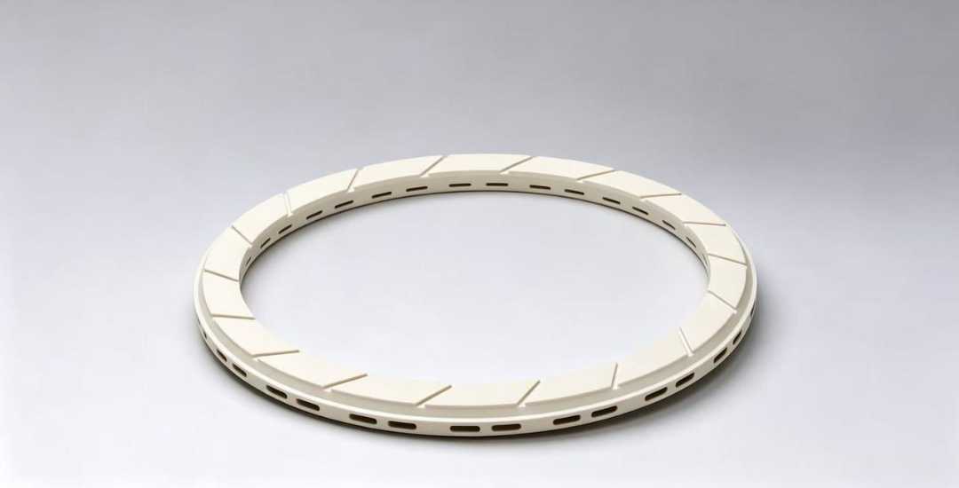
A 300 mm PEEK ring holds wafers during plasma etching. The sealing face requires flatness within 0.02 mm across the full diameter; any deviation creates a plasma leak that stops the process line. Locating bores at ±0.025 mm true position align with chamber pins. PEEK is chosen because it survives fluorine-based plasma without outgassing or eroding to contaminate the chamber, unlike aluminum.
A typical production sequence: stress-relieved plate inspected for flatness, rough milled to 1 mm stock on both faces for symmetry, full anneal with controlled ramp, vacuum fixturing to avoid clamping distortion, 24-hour stabilization, then CMM at 20 ± 1°C. Each ring ships with a full flatness map. If a ring warps, check the annealing ramp rate before blaming the machine.
Manufacturing focus: Flatness on large rings is stress management, not machine accuracy. Rings from the plate center hold tolerance more reliably.
Spinal Implant Trial
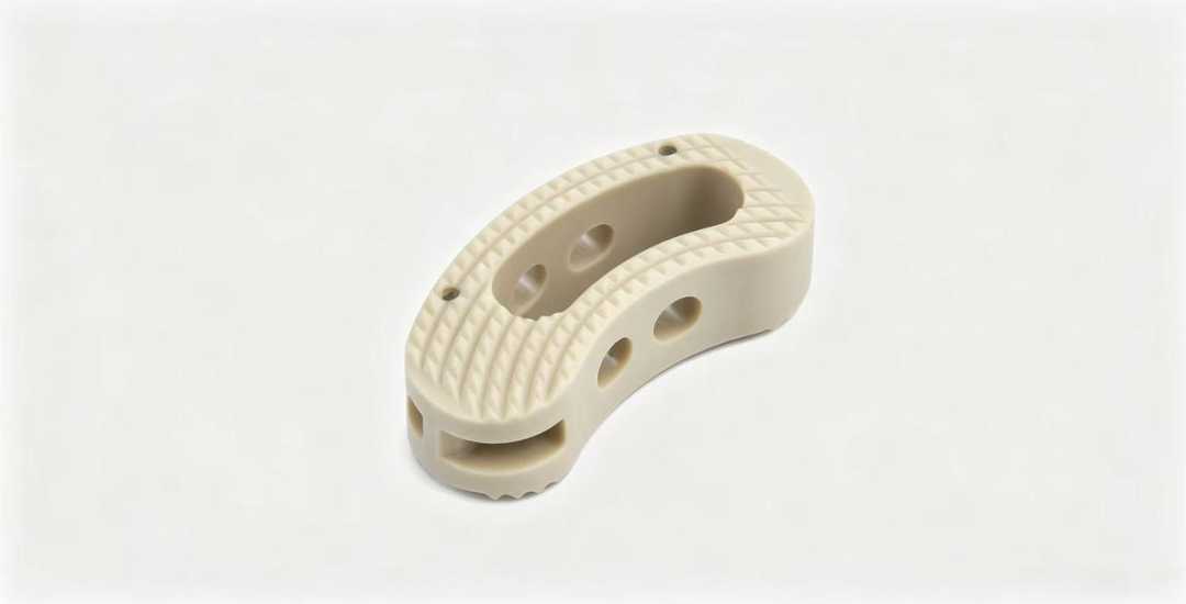
A temporary sizing instrument must match the final implant within ±0.025 mm on three critical features: interbody height, lordotic angle, and insertion stop face. Undersized, the surgeon selects a loose implant. Oversized, the implant will not seat. PEEK is chosen for radiolucency and durability through over 1,000 autoclave cycles.
For implant trial production, the rough-anneal-finish sequence is mandatory. Finish tools are replaced every 20 to 30 parts on a fixed interval, because tool wear on the angle surface is nearly invisible until the part goes out of tolerance. Every tenth part gets a full CMM check of all three features. Lot traceability links each trial to its stock batch and annealing cycle.
Manufacturing focus: Implant trial tolerances fail silently from tool wear. Replace tools by part count. Visual inspection catches wear too late for ±0.025 mm work.
6. Production Workflow for Repeatable PEEK Tolerances
Prototype capability is not production repeatability. Hitting a tolerance once on a first-article setup is different from holding it across 500 parts over six months. The practices below cover the three areas where production runs drift away from prototype results: tooling choices by grade, predictable failure modes and their fixes, and process discipline that keeps the workflow stable across batches.
Tooling by grade. Unfilled PEEK cuts cleanly with sharp, uncoated polished carbide. TiN and TiAlN coatings increase friction on most plastics, and on PEEK they typically degrade surface finish and chip evacuation. GF30 cuts tool life by half to two-thirds, so PCD becomes cost-effective above roughly 200 parts at 10 to 20x life. CF30 demands PCD as the practical minimum. Reducing cutting speeds by 20 to 30% for CF30 helps manage heat at the tool tip.
Common production problems and fixes.
- Chip rewelding in deep pockets and small holes. Use high-pressure air and peck drilling past 3x diameter depth.
- Surface crazing near sharp corners from excessive heat. Reduce depth of cut, add low-engagement finishing pass, verify stock annealing.
- Bore ovality on thin-walled parts from clamping. Use perimeter fixturing or vacuum workholding.
Recommended practices. Stress-relieve stock for tolerances tighter than ±0.076 mm, and switch to rough-anneal-finish below ±0.038 mm or with walls under 4 mm. Machine in a temperature-controlled shop and let parts soak at measurement temperature for minimum 2 hours before CMM. Document tool change intervals and stock lot numbers per batch, because dimensional drift across a run is more often a tool or material issue than a machine problem.
A typical precision PEEK production workflow: incoming stock inspection, pre-machining anneal, rough to 0.5–1.0 mm stock, intermediate anneal for sub-±0.025 mm work, finish with fresh carbide, 2–4 hour stabilization, CMM at 20 ± 1°C, lot release with full dimensional report.
Sources:Tool Manufacturer Technical Data、Victrex Machining Guide、Manufacturer Best Practices
7. Tolerance Tier Selection: How Tight Is Tight Enough
Tolerance selection is a cost decision, not just a drawing exercise. Each tightening step adds process steps that compound non-linearly. The table below maps three tolerance bands to the process controls they demand, from standard practice to full production discipline.
| Tier | Tolerance Range | דרישות תהליך | Relative Cost |
| תֶקֶן | ±0.1 mm and looser | Single anneal, no special controls | Baseline |
| דִיוּק | ±0.05 to ±0.025 mm | Rough-anneal-finish, shop ±3°C, tool monitoring, in-process checks | Moderate increase |
| Ultra-precision | Tighter than ±0.025 mm | Full variable control: intermediate anneal, fixed-interval tool changes, lot traceability, stabilization, CMM at 20 ± 1°C | Significant increase |
Note: Tolerance ranges and process requirements reflect typical CNC machining practice for engineering plastics. Cost estimates are approximate; actual cost depends on shop equipment, part geometry, and batch volume.
The right tolerance is the loosest the function allows, not the tightest the process can achieve. Tolerance tightening adds cost non-linearly.
Grade Selection by Feature and Requirement
The recommendations below summarize the grade behavior patterns discussed throughout this article. Final selection should consider the full service environment, including temperature, chemical exposure, and regulatory requirements.
| Condition | Recommended Grade | Key Reason |
| Small holes under 3 mm | Unfilled PEEK | Less tool wear variation than filled grades |
| Tight OD tolerance | GF30 or CF30 | Lower CTE holds OD during cutting |
| Flatness-critical large surfaces | CF30 | Highest stiffness resists warping |
| Cost-sensitive, moderate tolerance | Unfilled PEEK | Lowest material cost, easiest to rework |
| High stiffness, wear resistance | CF30 | Stiffness and abrasion resistance justify PCD tooling |
| Chemical exposure, high temperature | Unfilled PEEK (service-driven) | Service requirements override machining convenience |
Tolerance tier and grade selection work together. A tier defines how much process control the part needs, and the grade choice determines which features will hit that tier with the least trouble. Most tolerance problems start when these two decisions are made independently.
How to Specify Realistic PEEK Machining Tolerances
A tolerance callout on a PEEK drawing should start from what the part does in service, not from what looks tight on a print. Three steps cover most parts and keep cost proportional to function.
- Tag every feature as functional or not. A sealing groove width and a bore that mates with a metal pin are functional. A bolt clearance hole and a cosmetic fillet are not. Non-functional features should default to the loosest general tolerance the drawing allows. This single step eliminates most unnecessary tight callouts.
- Test the loose end. For each functional feature, ask what happens at the loose end of the tolerance band. If a bore is ±0.05 mm and the mating pin is clearance-fit, the part still works. If the same bore locates a bearing with zero clearance, ±0.05 mm may cause play or interference. The feature that fails at the loose end moves up one tier. The one that still works stays where it is.
- Count the tight features per part. A single tight feature adds one annealing step and some measurement discipline. Multiple tight features compound the process: three features at ±0.025 mm on one part typically means a full rough-anneal-finish sequence, controlled shop temperature, and CMM on every part. If only one of those three is truly functional, consider whether the other two can open up.
מַסְקָנָה
PEEK tolerance is not one number. The same part can hold ±0.01 mm on a turned diameter and struggle with ±0.05 mm on a deep pocket, because grade, feature geometry, stress history, and thermal conditions interact differently on every feature. The tolerance on the print is only as good as the process designed to hold it, and that process must be built around each feature individually, not copied from the material datasheet.
Beska has machined custom PEEK parts across all three grades and the full tolerance spectrum. The most common surprise we see: a part that works perfectly in unfilled PEEK fails in GF30 because nobody checked how the holes would behave after the grade switch. Send us your drawing or STEP file.
 Hebrew
 English
 Turkish
 French
 Russian
 German
 Spanish
 Portuguese