


In mechanical design and CNC machining, countersinks and counterbores are two common hole features used to accommodate fasteners. While both enlarge the entrance of a drilled hole, their geometry and functional purpose are fundamentally different.
A countersink creates a conical recess that allows flathead screws to sit flush with the surface. A counterbore forms a cylindrical recess with a flat bottom, typically used for socket head cap screws or other cylindrical fasteners.
Because these two features appear similar at first glance, they are sometimes confused in practice. However, in engineering drawings and precision manufacturing, the difference directly affects fastener compatibility, machining methods, and assembly performance.
The following sections examine the geometric characteristics, drawing symbols, machining processes, and typical applications of countersinks and counterbores.
1. Countersink vs Counterbore: Differences in Definition and Geometry

The distinction between a countersink and a counterbore begins with their geometric structure. Although both features enlarge the entrance of a drilled hole, their shapes and functional purposes are fundamentally different.
Countersink Geometry
A countersink is a conical recess created at the entrance of a drilled hole. The cone angle is designed to match the head angle of a flathead screw or other countersunk fastener.
Common standard angles include 82° (ANSI standard) and 90° (ISO standard), while other angles such as 60° or 100° are used in specific applications.
When a flathead screw is installed, its tapered head fits into the conical recess. After tightening, the screw head sits flush with the surface of the workpiece, creating a smooth exterior without protrusions.
Counterbore Geometry
A counterbore is a cylindrical stepped recess located at the top of a hole. It consists of a larger-diameter cylindrical cavity with a flat bottom, followed by a smaller through hole or blind hole underneath.
This feature is designed to accommodate cylindrical fastener heads, such as socket head cap screws or hex bolts. The recess allows the fastener head to sit below or flush with the surface while providing a flat bearing surface for load distribution.
Key Structural Difference
The essential difference between the two features lies in their geometry:
- Countersink: conical recess
- Counterbore: cylindrical recess with a flat bottom
Because of this difference, the two hole types interact with fasteners in different ways and transmit loads through the joint differently.
2. Key Characteristics of Countersinks and Counterbores
Although both features modify the entrance of a hole, countersinks and counterbores differ in geometry, dimensional parameters, and compatible fasteners. The main characteristics of each feature are summarized below.
| תכונה | Countersink | Counterbore |
| Geometry | Conical recess | Cylindrical recess |
| Sidewalls | Angled surfaces | Vertical walls |
| Bottom surface | No flat bottom for the cone section | Flat bottom |
| Compatible fasteners | Flat head screws, countersunk screws | Socket head cap screws, hex bolts |
| Key dimensions | Major diameter and included angle | Major diameter, depth, and hole diameter |
| Surface appearance | The screw head sits flush with smooth transition | Screw head recessed with visible circular edge |
These characteristics highlight the fundamental structural differences between the two features and explain why each is used in different fastening and assembly scenarios.
3. Countersink vs Counterbore: Standard Drawing Symbols and Notation
In engineering drawings, countersinks and counterbores are indicated using standardized symbols that define the geometry and dimensions of the hole feature. Accurate interpretation of these symbols is essential in machining and assembly, since they specify how the hole should be produced and which type of fastener it is intended to accommodate.
A countersink is typically represented by a V-shaped symbol placed before the countersink diameter and angle. A common notation may appear as: 4 × Ø6.5 ⌵ Ø12 × 90°
This specification indicates that:
- The part contains four holes with a through-hole diameter of 6.5 mm.
- Each hole includes a countersink with a major diameter of 12 mm.
- The included angle of the conical recess is 90°, which matches standard flat head screw angles used in ISO systems.
A counterbore is represented by a square U-shaped symbol, which specifies the diameter and depth of the cylindrical recess. A typical example may be written as: Ø10 ⌴ Ø15 ↧ 5
In this case:
- The base hole has a diameter of 10 mm.
- A counterbore with a diameter of 15 mm is machined at the top of the hole.
- The cylindrical recess has a depth of 5 mm, allowing the fastener head to sit below the surface.
These drawing conventions allow designers and machinists to communicate hole features clearly and ensure that the correct geometry is produced during machining.
4. Countersink vs Counterbore: Fastener Compatibility and Applications
The selection of a countersink or counterbore is determined mainly by the type of fastener and the functional requirements of the assembly.
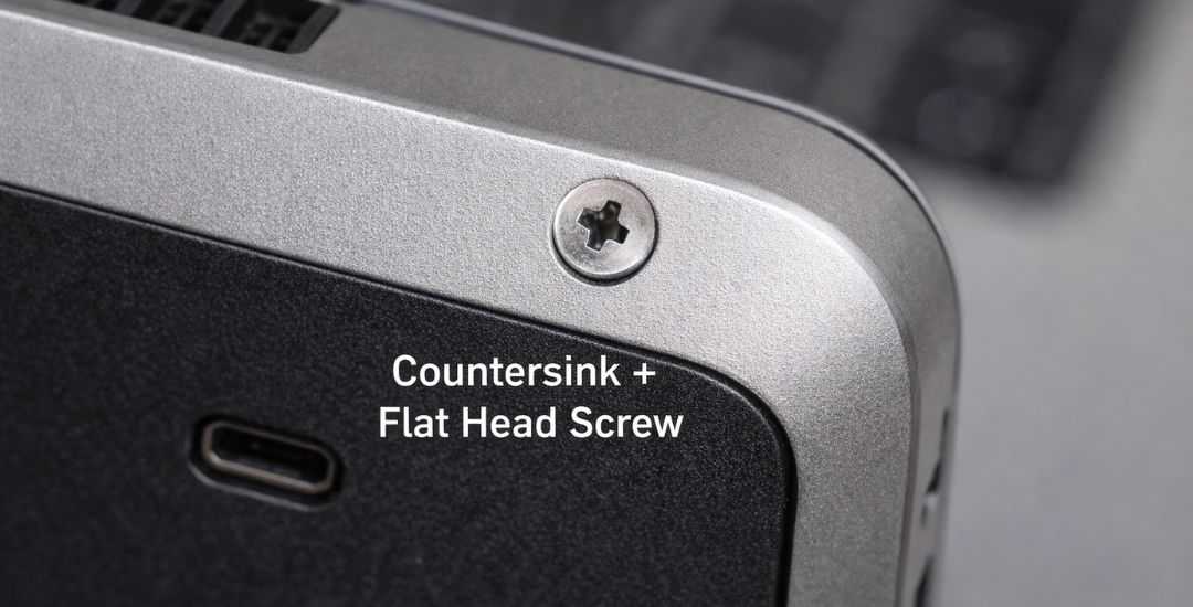
Countersinks are intended for flathead screws. The tapered head of these screws matches the conical surface of the countersink, allowing the screw to sit flush with the workpiece surface when tightened. This configuration is widely used in applications where surface smoothness or flush mounting is critical, such as:
- Aerospace panels, where aerodynamic performance is essential.
- Consumer electronics housings, requiring smooth external surfaces.
- Precision equipment covers, where protruding screws could interfere with moving parts.
- Furniture components that demand clean and aesthetically pleasing surfaces.
Any protruding screw head in these scenarios may create interference, compromise safety, or affect aesthetics.

Counterbores are designed for cylindrical fastener heads, including socket head cap screws, hex bolts, and bolts used with washers. The flat-bottomed cylindrical recess provides clearance for the fastener head while ensuring uniform load distribution across the contact surface. Typical applications include the following:
- Heavy machinery frames where high clamping force is required.
- Mold and die assemblies, which are subject to repeated assembly and disassembly.
- Automotive structures that experience vibration and shear loads.
- Equipment panels that require frequent maintenance access.
Socket head cap screws in counterbore assemblies allow for higher tightening torque, making this configuration suitable for joints subjected to high clamping forces or shear loads.
In some specialized designs, a small countersink may be added at the bottom of a counterbore to accommodate a chamfer or conical washer, although such configurations are relatively uncommon.
5. Machining Processes and Tool Selection for Countersinks and Counterbores
Countersinks and counterbores require different machining tools and processes due to their distinct geometries and functional roles.

Countersinks
Countersinks are generally created using countersink tools or drill bits with cutting edges set at a specific angle to match the screw head. For softer materials such as plastics or aluminum, multi-flute countersink tools efficiently produce the conical recess. In harder metals, single-flute or precision countersink cutters are preferred to ensure accurate angles and a smooth surface finish. Maintaining the correct cone angle is critical: if the countersink angle does not match the screw head, contact may occur only at the edge or near the bottom, which can result in unstable fastening or potential fastener damage.
Counterbores
Counterbores are machined using counterbore cutters, spotface tools, or end mills. The typical process involves drilling the initial hole, then enlarging the upper portion with a larger-diameter tool to form a cylindrical recess with a flat bottom. In some cases, combination drill-counterbore tools perform both operations in a single setup, improving production efficiency and alignment accuracy.
The differences in machining tools and methods reflect the distinct functional and geometric requirements of countersinks and counterbores. Proper tool selection and process control directly affect manufacturing efficiency and assembly reliability.
6. Countersinks vs Counterbores: Strength and Stress Distribution
The geometry of countersinks and counterbores affects how stress is distributed around a fastener, influencing both structural integrity and long-term reliability.
Countersinks
Countersinks remove material in a tapered, conical shape, and the removed volume increases rapidly as the recess deepens. In thin plates, deep countersinks can significantly reduce the effective cross-sectional area, potentially weakening the material.
Another consideration is the radial force generated by the conical interface. When a flat-head screw is tightened, the conical surfaces press against each other, producing outward radial forces. In brittle materials such as cast iron or certain composites, these forces can increase the risk of cracking around the hole. However, when the countersink is properly designed and matched with the screw, the conical interface also adds friction, which can help resist loosening over time.
Counterbores
Counterbores remove material in a cylindrical shape, resulting in a more uniform stress distribution around the fastener. The contact between the screw head and the flat bottom primarily transmits axial clamping force and shear loads, without significant radial expansion.
For structures subjected to dynamic loads, vibration, or repeated disassembly, counterbores paired with socket head cap screws are generally more reliable. In addition, counterbores tend to preserve more surrounding material compared with deep countersinks designed for the same fastener head depth, reducing the risk of weakening the component.
Countersinks and counterbores differ fundamentally in how they interact with fasteners and the surrounding material. Countersinks introduce radial forces that may challenge brittle components, while counterbores provide more uniform stress distribution and better preserve structural integrity, especially under repeated or heavy loading conditions.
7. Tolerance and Assembly Considerations for Countersinks and Counterbores
Manufacturing tolerances have a significant impact on how countersinks and counterbores perform during assembly. The two features differ in sensitivity to dimensional variations, affecting ease of installation and assembly reliability.
Countersinks
Countersinks require precise angular and diameter matching between the hole and the fastener head. Even minor deviations can cause issues such as screw heads not seating fully, uneven contact surfaces, or misalignment during tightening.
They are also sensitive to burrs at the hole entrance. Even small burrs can prevent the screw head from sitting flush with the surface, making deburring after machining a standard practice to ensure proper assembly.
Counterbores
Counterbores generally offer greater assembly tolerance. As long as the recess diameter is slightly larger than the screw head and the depth is sufficient, the fastener can be installed without difficulty. Typical design practice allows 0.2–0.5 mm of clearance between the screw head and the counterbore diameter. Because the fastener head rests on a flat surface, angular alignment is less critical, reducing the risk of assembly errors.
This tolerance advantage makes counterbores well-suited for automated or high-volume assembly, where minor dimensional variations are common and ease of installation is essential.
8. Surface Finishing and Coating Considerations
Surface finishing processes, such as painting, plating, or anodizing, can affect the performance and selection of countersinks and counterbores. Their geometry influences coating distribution and protection of the fastened assembly.
Countersinks
The angled surfaces of countersinks can impact coating thickness. Material may accumulate at the edge of the cone or become thinner along the sloped surface, potentially leading to uneven protection.
If the fastener is installed before finishing, masking may be required to prevent coating buildup around the screw head. If the fastener is installed after finishing, care must be taken to avoid damaging the coating at the hole entrance.
Counterbores
Counterbores generally allow more uniform coating coverage due to their flat, perpendicular surfaces. Coating processes such as powder coating or electrophoretic coating can distribute material evenly across the stepped geometry. In high-end applications, counterbores may be designed with additional depth to accommodate sealing compounds or fillers, improving corrosion resistance and surface integrity.
Surface finishing considerations are directly influenced by the feature geometry. Countersinks require careful attention to coating consistency due to angled surfaces, while counterbores naturally provide more uniform coverage and greater flexibility for sealing or protective compounds.
9. Design Selection Guidelines for Countersinks and Counterbores
The choice between a countersink and a counterbore largely depends on the functional priorities of the assembly. Countersinks are ideal when a smooth, flush surface is required. The conical recess allows flat head screws to sit neatly within the workpiece, making this feature suitable for aerospace panels, consumer electronics housings, and precision equipment covers.
Counterbores are more appropriate when mechanical strength, load distribution, or maintenance accessibility is the priority. The flat-bottomed cavity accommodates socket head screws or hex bolts, providing reliable fastening for heavy machinery, automotive structures, and assemblies that undergo frequent disassembly.
Material properties also influence selection. Brittle or composite materials benefit from counterbores, which avoid radial expansion forces that could cause cracking. From a production standpoint, counterbores are generally easier to machine and assemble, reducing complexity and cost in high-volume manufacturing.
Ultimately, the decision is guided by three main considerations: surface finish, mechanical performance, and material or production constraints. Evaluating these factors ensures the chosen feature aligns with both functional and manufacturing requirements.
מַסְקָנָה
Countersinks and counterbores each offer unique advantages depending on the fastener type, material, and assembly requirements. The conical design of countersinks ensures flush surfaces and smooth transitions, while counterbores provide flat-bottomed cavities that support higher loads and repeated maintenance. Proper specification of angles, depths, and standardized symbols on engineering drawings is essential to prevent assembly issues and maintain structural reliability.
Selecting the right hole feature not only optimizes mechanical performance but also simplifies manufacturing and assembly. For components requiring tight tolerances or complex geometries, consulting an experienced precision CNC machining partner like the Beska team can ensure that both countersinks and counterbores are executed accurately, supporting reliable and high-quality production.
Deeper into Our Resources
לקריאה מעמיקה, אספנו עבורך רשימה של מאמרים מומלצים:
 Hebrew
 English
 Turkish
 French
 Russian
 German
 Spanish
 Portuguese