


Hole-basis and shaft-basis systems are two standard ways to define fits between mating cylindrical parts. Both can produce clearance, transition, or interference fits. The difference is which tolerance zone stays at the zero line and which mating feature changes to create the required fit.
In most general mechanical designs, the hole-basis system is more common because standard hole tooling can be retained while the shaft size is adjusted to achieve different fits. A shaft-basis system becomes more practical when the shaft dimension is already fixed, such as a standard shaft, pin, or purchased component. The choice therefore affects how the fit is manufactured and inspected, even when the final assembly requirement is the same.
1. Hole Basis and Shaft Basis: Practical Definitions
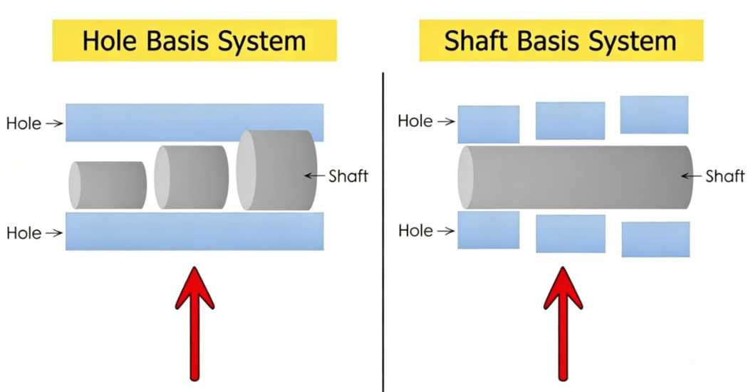
The difference between the two systems is not which part keeps the basic size. Both the hole and shaft are defined from the same nominal size. What changes is which tolerance zone is placed against the zero line.
Hole-Basis System
In a hole-basis system, the hole normally uses an H tolerance zone, which means its lower deviation, EI, is zero. Different clearance, transition, or interference fits are then created by changing the shaft tolerance zone.
This system is widely used because standard drills, reamers, gauges, and other hole-making tools can often be retained while the shaft dimension is adjusted to achieve different fits.
Shaft-Basis System
In a shaft-basis system, the shaft normally uses an h tolerance zone, where the upper deviation, es, is zero. The required fit is created by changing the tolerance zone of the mating hole.
This approach is useful when the shaft size is already fixed by a standard component, stock size, or existing design. Instead of changing the shaft, the hole tolerance is selected to produce the required clearance or interference.
2. Why the Hole-Basis System Is More Common
The hole-basis system is widely used in mechanical design mainly because it simplifies tooling and dimensional adjustment. A standard H hole can often be produced with common drills, reamers, boring tools, and gauges, while different fits are created by changing the shaft tolerance zone.
External diameters are also relatively convenient to adjust during turning or grinding. This makes it practical to keep the same hole specification and use different shaft sizes for clearance, transition, or interference fits without introducing multiple precision hole sizes.
This does not mean that hole-basis fits are inherently more accurate or more stable in batch production. Both hole and shaft dimensions are affected by tooling, machine capability, material condition, and process control. The main advantage of the hole-basis system is standardization and manufacturing convenience rather than superior dimensional stability.
3. ISO 286 Tolerance Zones and Fit Examples
Under ISO 286, the letter defines the position of the tolerance zone relative to the zero line, while the number defines the IT tolerance grade. A designation such as H7/g6 therefore combines an H7 hole with a g6 shaft.
In a hole-basis system, the hole uses an H tolerance zone and different shaft zones are selected to obtain the required fit. In a shaft-basis system, the shaft uses an h tolerance zone and the hole tolerance zone changes instead.
| Fit Type | Hole-Basis Example | Shaft-Basis Example |
| Clearance fit | H7/g6 | G7/h6 |
| Close clearance fit | H7/h6 | H7/h6 |
| Transition fit | H7/k6 | K7/h6 |
| Interference fit | H7/p6 | P7/h6 |
These combinations are representative examples rather than universal recommendations. The final tolerance classes should be selected according to nominal size, required clearance or interference, load, assembly method, and manufacturing capability.
4. DFM Considerations for Hole-Basis and Shaft-Basis Fits
The fit system should work in the way both mating features will actually be produced and inspected. Hole basis is often convenient when standard hole tooling can be used, while shaft basis can be practical when the shaft size is already fixed by a standard part or existing design.
Tooling and Feature Accessibility
Precision holes may require drilling, reaming, boring, honing, or שְׁחִיקָה depending on the tolerance and surface requirement. Deep holes, interrupted bores, and limited tool access can make a nominally simple H tolerance more difficult to produce.
Shaft dimensions also need to be matched to the available turning or grinding process. The easier feature to control depends on the geometry, tolerance grade, material, and machine capability rather than on the basis system alone.
Surface Treatment and Final Dimensions
Anodizing, plating, and other coatings can change the effective size of mating surfaces. These changes should be included in the tolerance calculation or controlled through masking where necessary.
Fit dimensions should therefore be evaluated in the final part condition, especially when the mating surfaces receive coating, heat treatment, or other processes after machining.
Inspection and Functional Requirements
A correct size tolerance does not always guarantee that two parts will assemble or operate as intended. Roundness, cylindricity, alignment, surface texture, and temperature can also affect the actual fit.
For critical assemblies, the drawing should define the fit together with any geometric or surface requirements needed to control the mating features.
5. Hole Basis vs Shaft Basis: Key Differences
The main difference between the two systems is which tolerance zone is held against the zero line and which mating feature is varied to create the required fit.
| Comparison | Hole-Basis System | Shaft-Basis System |
| Reference feature | Hole | Shaft |
| Basic tolerance zone | H hole | h shaft |
| Zero deviation | Lower deviation EI = 0 | Upper deviation es = 0 |
| Feature adjusted to change the fit | Shaft tolerance zone | Hole tolerance zone |
| Common manufacturing reason | Allows standard hole tooling to be retained | Useful when shaft size is already fixed or standardized |
| Typical use | General mechanical assemblies | Standard shafts, pins, or existing shaft dimensions |
Neither system is inherently more accurate, stable, or economical. Actual manufacturing cost and consistency depend on the tolerance grade, part geometry, material, tooling, inspection method, and production process.
6. When to Use Hole-Basis and Shaft-Basis Fits
The choice usually comes down to which mating feature is easier or more practical to keep standardized.
When a Hole-Basis Fit Makes Sense
Hole-basis fits are common in general mechanical assemblies where standard hole sizes can be produced with readily available drills, reamers, boring tools, and gauges. Different clearance, transition, or interference fits can then be created by changing the shaft tolerance zone.
This approach works well for many machined housings, brackets, bearing seats, locating features, and other assemblies where the hole design remains unchanged while the mating shaft size can be adjusted.
When a Shaft-Basis Fit Makes Sense
Shaft-basis fits become useful when the shaft diameter is already fixed by a standard component, purchased part, stock size, or existing design. In that case, changing the hole tolerance is often more practical than modifying the shaft itself.
Typical examples include assemblies built around standard pins, shafts, or other components whose outside diameter should remain unchanged while different mating parts require different fits.
7. Common Mistakes When Specifying Fits
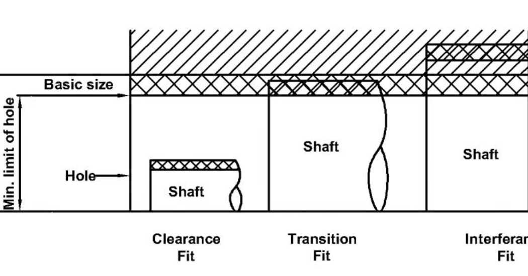
Fit problems usually come from the way tolerances are specified and manufactured rather than from choosing hole basis or shaft basis alone. Several issues deserve attention before the drawing is released.
Choosing the Fit Before Defining Its Function
A clearance, transition, or interference fit should be selected according to how the parts need to assemble and operate. Sliding, accurate location, torque transmission, and permanent pressing require different fit conditions.
The basis system should be chosen after the required relationship between the two mating parts is clear.
Relying on Size Tolerance Alone
A correct ISO fit designation does not automatically guarantee proper assembly. Roundness, cylindricity, alignment, and surface texture can also affect the actual contact between mating features.
These requirements become especially important for precision bores, long engagement lengths, and assemblies where alignment directly affects function.
Ignoring Post-Processing Changes
Anodizing, plating, heat treatment, and other secondary processes can change mating dimensions or introduce distortion. Fit dimensions should therefore be evaluated in the final part condition rather than only from the machined size.
Masking, machining allowance, or post-process finishing may be needed where the fit must remain tightly controlled.
Using Standard Fit Codes Without Checking the Actual Size Range
A designation such as H7/g6 does not correspond to one fixed clearance value. The actual tolerance limits change with the nominal diameter range.
For critical assemblies, the expected minimum and maximum clearance or interference should be calculated rather than relying on the fit code alone.
מַסְקָנָה
A fit only works when both mating features are produced as intended. The ISO designation defines the size relationship, but tool access, part geometry, surface condition, and secondary processing can still influence the final assembly.
For parts with precision bores, shafts, locating features, and other mating surfaces, Beska combines כרסום CNC and turning with appropriate hole-finishing processes and dimensional inspection. These requirements can be considered during process planning so that the specified fit is practical to machine, measure, and assemble.
 Hebrew
 English
 Turkish
 French
 Russian
 German
 Spanish
 Portuguese