


Surface roughness and surface finish are often confused in עיבוד CNC, even though they describe different characteristics of a machined surface. The difference directly affects drawing specifications, manufacturing cost, and the final performance of machined components.
In engineering drawings, these terms have different meanings. Surface roughness refers to measurable surface texture parameters such as Ra and Rz, while surface finish is a broader term that may include roughness, waviness, lay, or post-machining treatments such as polishing and coating. Using the wrong specification can result in unnecessary finishing operations, sealing issues, or premature wear.
This article explains the difference between surface roughness and surface finish, how roughness is measured, and how to specify practical surface requirements for CNC machined components.
1. Surface Roughness vs. Surface Finish: Clarifying the Terms
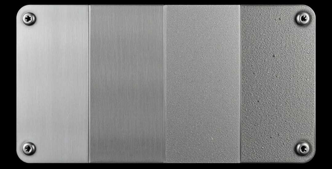
Surface roughness is a quantitative measurement of the microscopic peaks and valleys left on a machined surface. These irregularities are influenced by factors such as tool geometry, feed rate, cutting speed, and machining conditions. Roughness is typically expressed in micrometers (µm) or microinches (µin) and reported using parameters such as Ra (Roughness Average).
Surface finish is a broader description of the overall surface condition of a part. In engineering, it may include roughness, waviness, and lay (the dominant direction of tool marks). In shop-floor conversations, the term may also be used more broadly when referring to post-machining processes such as polishing, אילגון, plating, or coating.
Surface texture consists of three main elements: roughness (fine surface irregularities), waviness (larger deviations caused by vibration or machine conditions), and lay (the direction of the surface pattern). Roughness is the parameter most commonly specified on engineering drawings, but waviness can also affect performance on large sealing or precision surfaces.
The practical difference is simple: surface roughness is a measurable parameter, while surface finish describes the overall surface condition. Using the correct terminology on drawings helps prevent miscommunication and unnecessary manufacturing costs.
2. Key Surface Roughness Parameters: Ra, Rz, and Rq
When a drawing specifies surface roughness, Ra is the most common parameter, while Rz and Rq are used for applications where average roughness alone may not provide enough information. Each parameter describes a different aspect of the surface profile.
- Ra (Roughness Average) is the most widely used parameter. It represents the arithmetic average of the absolute deviations of the surface profile from the mean line over a defined sampling length. Ra is easy to measure and compare, but because it is an average value, two different surface profiles can have the same Ra result.
- Rz (Mean Roughness Depth) measures the average peak-to-valley height from the five largest surface irregularities within the sampling length. It is more sensitive to isolated scratches or high points and can provide additional control for surfaces where individual defects may affect performance.
- Rq (Root Mean Square Roughness) is the RMS value of surface profile deviations. Compared with Ra, it gives more weight to larger peaks and valleys. It is mainly used for statistical analysis or legacy specifications.
| פָּרָמֶטֶר | Measures | יישומים אופייניים |
| Ra | Average surface deviation from the mean line | General CNC surface roughness specification |
| Rz | Average peak-to-valley height | Sealing surfaces and scratch-sensitive applications |
| Rq | RMS surface deviation | Statistical analysis and legacy drawings |
For most CNC machining applications, Ra is the default surface roughness parameter. However, critical applications should specify the required parameter clearly to avoid different interpretations between design and manufacturing teams.
For dynamic sealing applications, specifying both Ra and Rz can provide better control. Ra describes the overall surface texture, while Rz helps identify larger peaks that may damage the seal lip.
Source: ASME B46.1 and ISO 4287 roughness parameter definitions.
3. How Surface Roughness Is Measured
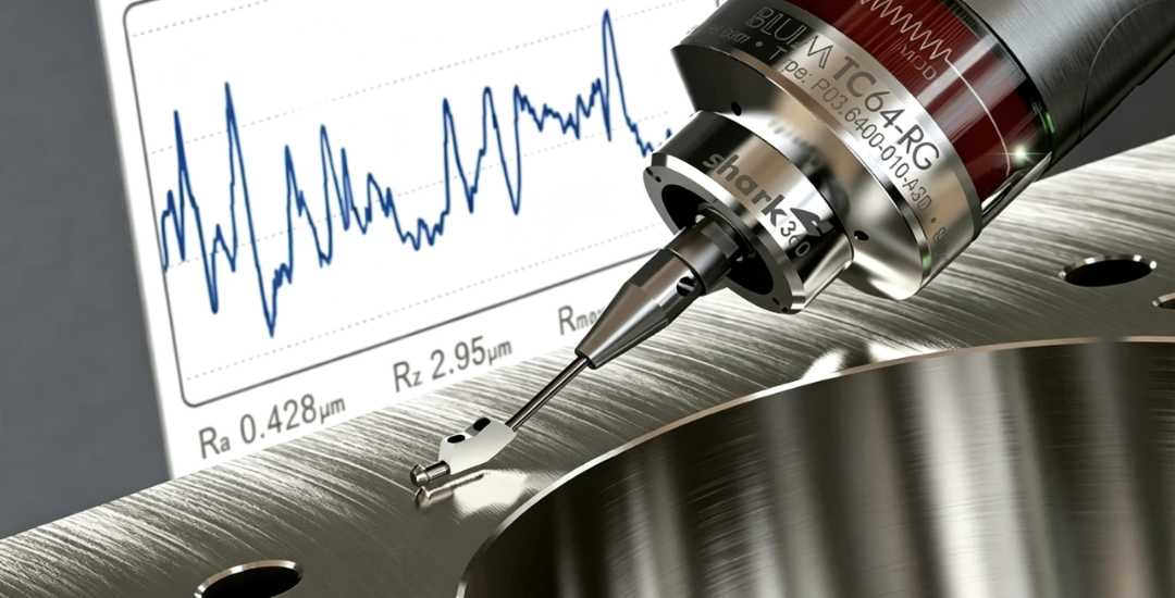
Surface roughness is measured using a profilometer, which records surface deviations along a defined measurement length. A contact profilometer uses a diamond stylus to trace the machined surface and calculate parameters such as Ra and Rz based on the measured profile.
Contact profilometry remains the most common method in CNC machining בקרת איכות because it provides repeatable measurements across a wide range of metals and engineering materials. Measurement conditions, including sampling length and measurement direction, should be selected according to the surface requirements and applicable standards such as ASME B46.1 and ISO 4287.
Optical profilometry uses light instead of physical contact to capture surface data. It is useful for delicate materials, complex geometries, or applications requiring three-dimensional surface analysis, although it is less common for routine shop-floor inspection due to equipment cost and setup requirements.
For most CNC machined components, contact profilometry provides the practical balance between accuracy, repeatability, and inspection efficiency.
4. Why Surface Roughness Matters for Part Performance
Surface roughness is not only a cosmetic requirement. It directly affects sealing performance, wear behavior, fatigue life, coating performance, and manufacturing cost.
Sealing Performance
Surface texture plays an important role in sealing applications. A surface that is too rough may create leakage paths, while an excessively smooth surface may not retain enough lubricant in dynamic sealing conditions. Shaft seals, pistons, and hydraulic components often require tighter surface control than static sealing applications such as flanges or gaskets.
Fatigue Life
Surface irregularities can act as stress concentrators where cracks may initiate under repeated loading. In high-cycle applications, surface roughness requirements are often determined by fatigue performance rather than appearance or sealing requirements.
Wear and Friction
A rough surface can increase friction and accelerate wear, but smoother is not always better. The ideal surface condition depends on factors such as lubrication method, contact pressure, and operating environment.
Coating Adhesion
Surface texture also influences coating performance. Processes such as plating, anodizing, and painting require appropriate surface preparation to achieve reliable adhesion. Surface conditions that are too smooth or too rough may reduce coating performance.
Appearance
For visible components, surface roughness affects the perceived quality of the part. However, specifying a finer finish than necessary increases manufacturing cost without improving function.
A common mistake in CNC projects is specifying Ra 0.8 µm on every surface simply as a safety margin. In many cases, only functional surfaces require this level of finish, while non-critical areas can remain at Ra 3.2 µm to reduce machining time and cost.
5. How Surface Roughness Affects CNC Machining Cost
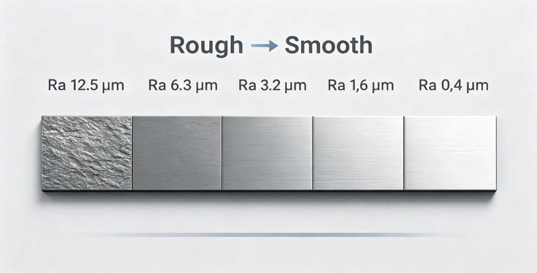
Tighter surface roughness requirements generally increase manufacturing cost. Achieving finer finishes often requires slower cutting parameters, additional finishing passes, sharper tooling, and sometimes secondary processes such as grinding or polishing.
A Ra 3.2 µm surface is a common standard for general CNC machining. It may show visible tool marks but is suitable for many non-critical surfaces.
Moving to Ra 1.6 µm often requires additional finishing operations and tighter process control. Achieving Ra 0.8 µm or finer may require specialized tooling, grinding, honing, or other finishing methods depending on the material, geometry, and production requirements.
For most CNC projects, the goal is not to achieve the lowest possible roughness value. The goal is to specify the surface requirement that matches the actual function of the part. Applying ultra-fine finishes to non-critical surfaces increases cost without improving performance.
In production reviews, we often find that some surface requirements are specified more tightly than the application requires. Re-evaluating functional surfaces and relaxing unnecessary roughness requirements can reduce finishing operations while maintaining part performance.
6. How to Specify Surface Roughness on Engineering Drawings
Surface roughness requirements are indicated on engineering drawings using surface texture symbols defined by ISO 1302. The required roughness value, such as Ra 3.2, is placed with the symbol to define the expected surface condition.
The symbol variations communicate how the surface should be produced:
| Symbol | Meaning |
| Basic symbol | Surface may be produced by any method |
| Symbol with a horizontal bar | Material removal is required, such as machining |
| Symbol with a circle | Material removal is not allowed, such as cast or molded surfaces |
Additional information can be added to specify lay direction, manufacturing method, or machining allowance. However, for most CNC machining drawings, the roughness value and surface texture symbol are sufficient.
In many CNC applications, Ra is commonly assumed when no parameter is specified. For surfaces sensitive to isolated peaks, such as sealing or optical applications, the required parameter should be stated clearly, for example: Ra 0.8 with Rz max 12.5.
Clear surface requirements help machinists select appropriate tooling, cutting parameters, and finishing processes before production begins, reducing unnecessary adjustments and inspection issues.
7. Common Surface Roughness Values in CNC Machining
The following table provides typical surface roughness ranges achievable with common CNC machining processes. These values serve as a practical reference when preparing designs, reviewing drawings, and evaluating manufacturing requirements.
| Ra Value | תֵאוּר | Typical Process | Relative Cost Impact |
| Ra 3.2 µm | Standard machined surface, visible tool marks | Standard milling / turning | נָמוּך |
| Ra 1.6 µm | Smoother machined surface with reduced tool marks | Fine milling, finishing pass | לְמַתֵן |
| Ra 0.8 µm | Very smooth machined surface with minimal visible marks | Fine finishing, light polishing | גבוה יותר |
| Ra 0.4 µm | Precision surface for demanding applications | Fine boring, honing, grinding | גָבוֹהַ |
| Ra 0.2 µm | Precision ground surface | Surface grinding | גבוה מאוד |
Source: Typical CNC machining surface finish ranges based on industry practices and surface texture standards including ASME B46.1 and ISO 21920.
These values are typical references only. Actual results depend on material, tooling, machine condition, geometry, and machining strategy. For example, aluminum is generally easier to finish than stainless steel, while engineering plastics such as POM can achieve very smooth surfaces with appropriate tooling and cutting parameters.
Lower roughness requirements usually require additional process control and finishing operations. The most economical approach is to specify the surface condition required by the function of the part rather than selecting the lowest possible Ra value.
8. Ra vs Rz: Why Direct Conversion Is Not Always Reliable
Ra and Rz describe different characteristics of a surface profile, so they cannot be converted using a fixed mathematical formula. Two surfaces may have the same Ra value but different peak-to-valley characteristics, resulting in different Rz values.
Approximate Ra-to-Rz relationships are sometimes used as general references, but the actual relationship depends on machining process, material, tool condition, and surface texture.
| פָּרָמֶטֶר | Measures | Why It Matters |
| Ra | Average surface deviation | Common general-purpose roughness specification |
| Rz | Average peak-to-valley height | More sensitive to scratches and isolated surface defects |
For critical functional surfaces, do not rely on approximate conversions. Specify the required parameter directly on the drawing, such as Ra 0.8 µm or Rz max 12.5 µm, depending on the application requirements.
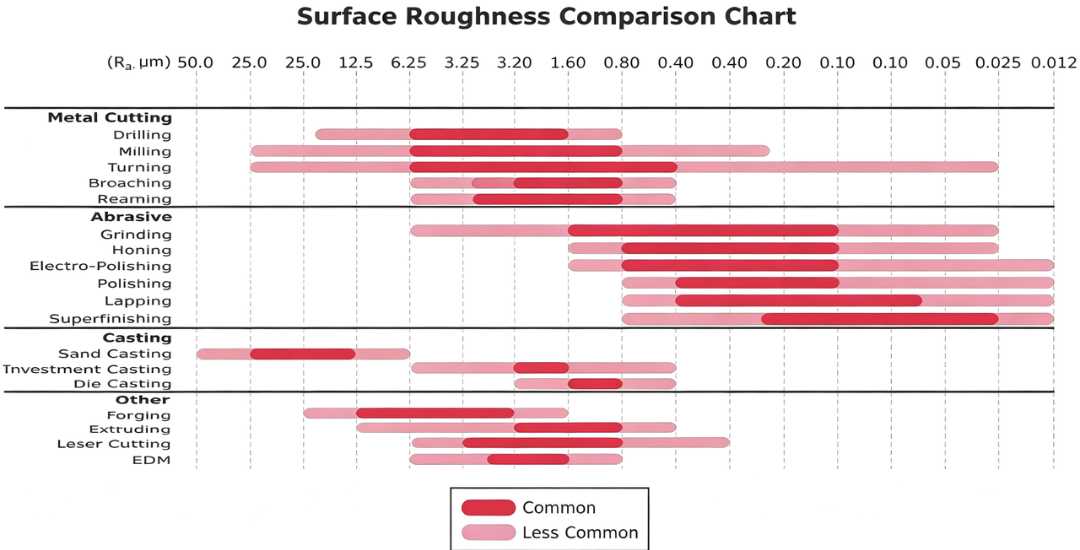
9. Choosing the Right Surface Roughness for Your Application
The following recommendations provide a practical starting point when defining surface requirements for machined components. Actual requirements depend on factors such as load, lubrication, sealing method, material, and operating conditions.
Application Type | Recommended Ra | Why |
Structural surfaces, non‑critical | Ra 3.2 µm | Cost‑effective, standard machining |
Sliding surfaces, moderate precision | Ra 1.6 µm | Reduces friction without excessive cost |
Sealing surfaces (static seals) | Ra 0.8–1.6 µm | Prevents leakage, retains some lubricant |
Sealing surfaces (dynamic seals) | Ra 0.2–0.4 µm | Minimizes wear, maintains seal life |
Bearing surfaces, high precision | Ra 0.4 µm or finer | Requires grinding or honing |
Decorative / consumer‑facing | Ra 1.6 µm or better | Visual quality matters |
Source: Common engineering surface texture practices based on ISO 1302 and ASME B46.1.
Surface roughness should be selected according to the function of each surface rather than applying the finest possible finish everywhere. Excessively tight roughness requirements increase machining time and cost without improving part performance when the surface has no functional requirement.
Post-processing should also be considered when defining surface requirements. Processes such as anodizing, plating, and coating can change the final surface condition. If the roughness requirement applies after finishing, the machining process should be planned accordingly.
10. Our Experience with Surface Roughness Specifications
Surface roughness requirements are often one of the first details we review during CNC project evaluation. In many drawings, the challenge is not achieving a lower Ra value, but determining whether that requirement is necessary for the actual function of the part.
Our standard CNC machining process typically achieves Ra 3.2 µm for general machined surfaces. When tighter requirements such as Ra 1.6 µm or finer are needed, the process may require optimized cutting parameters, dedicated finishing tools, or secondary operations such as grinding and lapping.
One common issue we see in project reviews is that some surfaces are specified with tighter roughness requirements than the application requires. Functional areas such as sealing surfaces, bearing interfaces, and sliding contacts may need a finer finish, while non-critical surfaces can often remain at standard machining finishes. Reviewing these requirements early can help reduce unnecessary finishing operations while maintaining part performance.
מַסְקָנָה
Surface roughness should be specified according to the function of the part, not simply based on achieving the smoothest possible surface. A properly selected surface requirement helps balance performance, manufacturing time, and overall cost.
In most CNC machining projects, standard finishes such as Ra 3.2 µm are suitable for general surfaces, while tighter requirements should be reserved for functional areas such as sealing surfaces, bearing interfaces, and precision fits. The goal is not the lowest possible Ra value, but the correct surface condition for the application.
At Beska, we review surface requirements together with part function, material, and manufacturing process to help customers avoid unnecessary finishing operations while maintaining required performance.
 Hebrew
 English
 Turkish
 French
 Russian
 German
 Spanish
 Portuguese