


A bolt and nut are the simplest examples of external and internal threads. The bolt carries threads on its outside surface, while the nut provides the matching thread inside a hole. They work as a pair, but the two features are designed, machined, and inspected in different ways.
Internal threads bring concerns such as engagement length, hole depth, chip evacuation, and access for inspection. External threads require attention to runout, relief, root geometry, and the condition of the exposed thread surface. This article looks at those differences through thread design, manufacturing, inspection, and common failure modes.
1. What Is Internal Thread?
An internal thread is a helical thread formed on the inside surface of a hole. It mates with an external thread on a bolt, screw, or stud to create a threaded connection.
Common examples include nuts, tapped holes, and threaded inserts. Internal threads may be produced directly in the parent material or added with an insert when the design requires different strength, wear resistance, or repairability.
Compared with an exposed external thread, the internal thread sits inside a hole, so its geometry is less accessible during manufacturing and inspection. The detailed design and machining requirements depend on the thread size, material, hole type, and application.
2. What Is External Thread?
An external thread is a helical thread formed on the outside surface of a cylindrical part. Common examples include bolts, screws, studs, threaded shafts, and fittings.
It mates with an internal thread to create a threaded connection. Because the thread is exposed on the outside surface, its geometry is generally easier to access during manufacturing and inspection than an internal thread.
External threads can be produced on both standard fasteners and custom machined parts, with the exact thread form, pitch, and tolerance defined by the applicable drawing or thread standard.
3. Internal Thread vs External Thread: Key Differences
Internal and external threads form the two mating sides of a threaded connection. Their thread profile and pitch must be compatible, but their location changes how they are designed, machined, and inspected.
| Comparison | Internal Thread | External Thread |
| Location | Formed inside a hole or nut | Formed on the outside of a shaft, bolt, screw, or stud |
| Mating Function | Receives the external thread | Engages with the internal thread |
| Accessibility | Located inside a hole, with more limited tool and inspection access | Exposed on the outside surface and generally easier to access |
| Typical Manufacturing Methods | Tapping, thread milling, single-point threading | Thread rolling, single-point cutting, dies, grinding |
| Inspection Approach | Commonly checked with plug or indicating gauges | Commonly checked with ring gauges, thread micrometers, or other external measurements |
| Main Design Concerns | Engagement length, hole depth, wall thickness, and blind-hole clearance | Thread runout, relief near shoulders, root geometry, and available threaded length |
| Common Failure Concerns | Thread stripping, wear, galling, or damage to the surrounding material | Root fatigue, crest damage, stripping, wear, or galling |
The main difference is therefore not that one type is inherently stronger or better. Internal threads usually require more attention to the material surrounding the hole and the available engagement length, while external threads bring their own concerns around root stress, runout, and exposed thread damage.
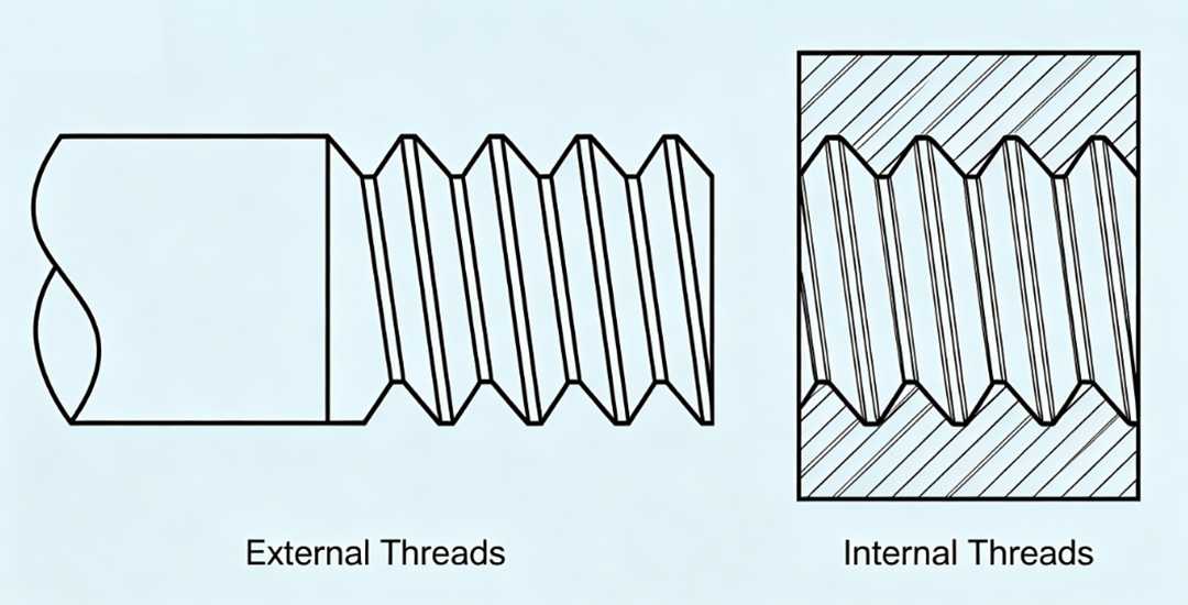
Both sides should be considered together. Material strength, thread size, pitch, fit, engagement, and service load determine how the complete threaded joint performs.
4. Common Thread Standards and Forms
Internal and external threads must use compatible thread forms, pitches, and tolerance systems to mate correctly. A thread that looks similar in size may still be incompatible if it follows a different standard.
| Thread Standard / Form | Profile Angle | Typical Use | Key Point |
| ISO Metric (M) | 60° | General machinery, automotive, equipment, fasteners | Widely used for metric threaded connections |
| Unified (UNC / UNF) | 60° | Machinery, industrial equipment, aerospace, inch-based fasteners | UNC uses a coarser pitch, while UNF uses a finer pitch for the same nominal diameter |
| NPT | 60° | Pipe and fluid connections | Tapered thread designed to create sealing engagement |
| BSPP / BSPT | 55° | Pipe fittings and fluid systems | BSPP is parallel, while BSPT uses a tapered form |
| Trapezoidal (Tr) | 30° | Lead screws and power transmission | Designed more for motion and load transfer than for fastening |
These thread systems should not be treated as interchangeable. A metric thread will not mate correctly with a Unified thread of similar diameter, and pipe threads must match the intended sealing system as well as the nominal size.
The standard also defines more than thread angle. Pitch, major and minor diameters, tolerance class, fit, and inspection requirements all form part of the thread specification. For machined parts, the drawing should therefore identify the complete thread designation rather than only the nominal diameter.
5. Design Considerations for Internal and External Threads
A thread may follow a standard profile, but the surrounding geometry still determines whether it can be manufactured, assembled, and loaded reliably. Engagement length, blind-hole clearance, wall thickness, runout, and thread fit all need to be considered as part of the joint rather than as separate dimensions.
Thread Engagement
Thread engagement determines how much of the internal and external thread shares the load. Too little engagement can increase the risk of thread stripping, especially when a stronger steel fastener is used in a softer material such as aluminum.
There is no single engagement ratio that works for every material pair. The required length depends on thread size and pitch, the strength of both materials, and the load carried by the joint. Softer internal-thread materials may require more engagement than higher-strength materials.
Extra thread length also stops adding useful strength once the joint is already limited by another feature, so engagement should be based on the actual load requirement rather than simply made as long as possible.
Blind-Hole Depth and Tool Clearance
A blind threaded hole needs more depth than the usable thread length shown on the drawing. Space is also required for the tool entry geometry, chip accumulation, and the bottom of the drilled hole.
The exact allowance depends on how the thread is produced. A cutting tap, forming tap, thread mill, or single-point tool may require different clearances, so one fixed hole-depth formula should not be applied to every process.
Providing enough depth from the beginning avoids situations where the specified full thread cannot be produced without changing the tooling or hole geometry.
Wall Thickness and Surrounding Material
Internal threads rely on the material surrounding the hole to carry the load. Thin walls can deform or crack if the remaining section is not sufficient for the thread size and applied load.
Instead of applying one fixed wall-thickness ratio, the section should be evaluated using the material strength, thread diameter, engagement length, and distance to nearby edges or features. This is particularly important in lightweight housings and other thin-wall components.
External Thread Runout and Relief
External threads that terminate near a shoulder need enough space for the cutting or grinding tool to exit the threaded region.
If the thread runs directly into a shoulder, the last turns may be incomplete. A suitable relief or undercut can provide tool clearance and allow the mating component to reach the intended seating surface.
The required relief geometry depends on the thread form, manufacturing method, and drawing requirements rather than being identical for every external thread.
Thread Fit and Tolerance
Internal and external threads also need compatible tolerance classes. A thread that is too tight may create assembly problems, while excessive clearance can reduce positional control or affect how the joint behaves under load.
The drawing should therefore specify the complete thread designation, including the required tolerance or fit class where applicable. Internal and external threads should be treated as a mating pair rather than dimensioned independently.
6. How Internal and External Threads Are Made
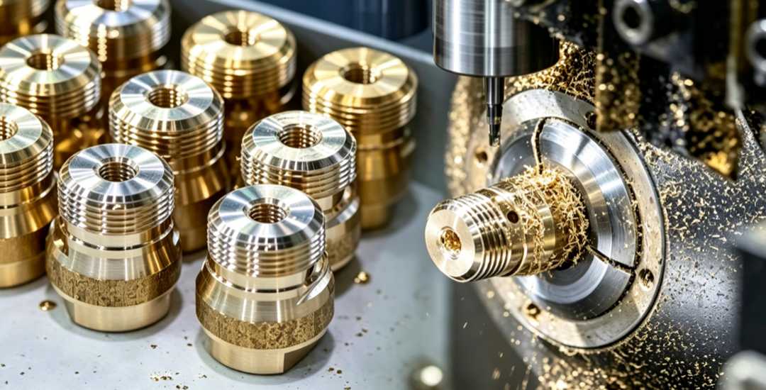
Internal and external threads can be produced by several thread machining and forming methods. The process depends on the thread size, material, tolerance, production quantity, and whether the thread is located inside a hole or on an exposed surface.
External Thread Manufacturing
External threads can be produced by thread rolling, single-point cutting, dies, or grinding.
Thread rolling forms the thread by pressing the workpiece between hardened dies rather than removing material. It is widely used for repeat production because it is fast, produces no chips, and can provide favorable surface and fatigue characteristics.
Single-point threading is commonly used on CNC lathes for custom sizes, lower quantities, or parts where flexibility is important. Threading dies are another practical option for simpler external threads, while thread grinding is used when very tight dimensional control or fine surface quality is required.
Internal Thread Manufacturing
Internal threads are commonly produced by tapping, thread milling, or single-point threading.
Tapping uses a tool with the complete thread profile to form or cut the thread in a pre-machined hole. It is efficient for many standard thread sizes, but tool breakage and chip evacuation need more attention, especially in blind holes.
Thread milling uses a rotating cutter that follows a helical toolpath. It provides more flexibility for thread size, depth, and material, and a single cutter may be used for more than one thread diameter when the pitch is compatible.
Single-point internal threading is often used on larger bores, custom thread forms, or parts already being machined on a lathe.
Why the Machining Conditions Differ
The main difference comes from access. External threads are exposed, giving the tool more room and making chip removal and visual inspection easier.
Internal threads are machined inside a hole, where tool reach, chip evacuation, coolant delivery, and bottom clearance can become more restrictive. Blind holes make these conditions even more important because chips and tooling must share the same limited space.
For both thread types, the manufacturing method should be selected around the material, geometry, tolerance, and production requirements rather than assuming that one process is always the best choice.
7. How Threads Are Inspected
Thread inspection checks whether the internal and external threads meet the required size, fit, and tolerance. The main difference is access: external threads are exposed, while internal threads must be checked inside a hole.
External Thread Inspection
External threads can be inspected with thread ring gauges, thread micrometers, or the three-wire method, depending on the required level of measurement.
Go/no-go ring gauges are commonly used to confirm whether a thread falls within the specified tolerance. Thread micrometers provide a practical way to measure pitch diameter, while the three-wire method is often used when a more detailed dimensional check is required.
Visual inspection can also identify damaged crests, burrs, incomplete threads, or surface defects before final gauging.
Internal Thread Inspection
Internal threads are commonly checked with thread plug gauges. A go/no-go plug gauge verifies whether the thread falls within the specified limits without providing a numerical measurement.
Where actual thread dimensions are required, indicating gauges or other specialized measurement methods may be used. The inspection method should match the thread tolerance, size, depth, and quality requirements of the part.
Blind holes may require additional attention because the full thread length and bottom condition are less accessible than in through holes.
Inspection Access and Thread Fit
External threads generally provide easier access for direct measurement, while internal threads rely more heavily on gauges that enter the threaded hole.
The goal is not simply to measure one side independently. Internal and external threads must fit within compatible tolerance classes so that the assembled joint provides the intended clearance or interference.
For production parts, the drawing should define the thread standard and tolerance class clearly so the correct gauges and inspection method can be selected.
8. Common Thread Failure Modes
Threaded joints can fail through stripping, fatigue cracking, galling, or gradual wear. Which failure appears first depends on the materials, thread geometry, engagement length, preload, and service conditions.
Thread Stripping
Thread stripping occurs when the engaged thread flanks can no longer carry the applied shear load. Either the internal or external thread may fail first, depending on the relative material strength and engagement length.
This risk is especially important when a high-strength steel fastener is used in a softer material such as aluminum. Sufficient engagement and adequate surrounding material help reduce the chance of pull-out or thread damage.
Fatigue Cracking
Threads create local stress concentrations, particularly around the thread roots and transition areas. Under repeated cyclic loading, small cracks can begin at these locations and gradually grow.
Proper preload, smooth thread runout, and suitable thread geometry can help reduce fatigue risk, especially in joints exposed to vibration or repeated loading.
Galling
Galling is a form of adhesive wear that occurs when mating thread surfaces slide under pressure and material begins to transfer between them. In severe cases, the threads can seize during tightening or removal.
Stainless steel thread pairs are particularly susceptible. Lubrication, suitable coatings, controlled tightening, and appropriate material combinations can help reduce the risk.
Thread Wear and Deformation
Repeated assembly and disassembly can gradually wear the thread flanks, while excessive tightening may cause local plastic deformation.
Over time, these changes can increase clearance, reduce preload, or make the joint less reliable for reuse. Thread inserts or harder mating materials.
Conclusion
Internal and external threads work as a mating pair, but they place different demands on design, machining, and inspection. Internal threads require careful attention to engagement, hole depth, and surrounding material, while external threads bring their own concerns around runout, root geometry, and exposed thread condition.
A reliable threaded joint comes from matching the thread form, tolerance, material, engagement, and manufacturing method to the actual service conditions. Treating both sides of the connection as one system helps reduce problems such as stripping, fatigue cracking, galling, and premature wear.
 English
 Hebrew
 Turkish
 French
 Russian
 German
 Spanish
 Portuguese