


A machined wall becomes “thin” when its stiffness drops low enough that cutting forces, clamping pressure, or heat push it out of position. There is no single wall thickness that defines this transition because stiffness depends on geometry as much as thickness. A 1 mm wall supported on three sides may machine cleanly, while the same wall with a large unsupported height can deflect, chatter, and taper.
A wall that deflects during machining may measure correctly in the fixture but fall outside tolerance after unclamping or CMM inspection. The result is higher scrap rates, additional rework, and longer production time.
This guide explains why thin walls deflect, chatter, and warp, along with practical design rules, workholding methods, machining strategies, and real-world examples that help improve dimensional accuracy and machining stability.
1. What Is Thin Wall Machining?
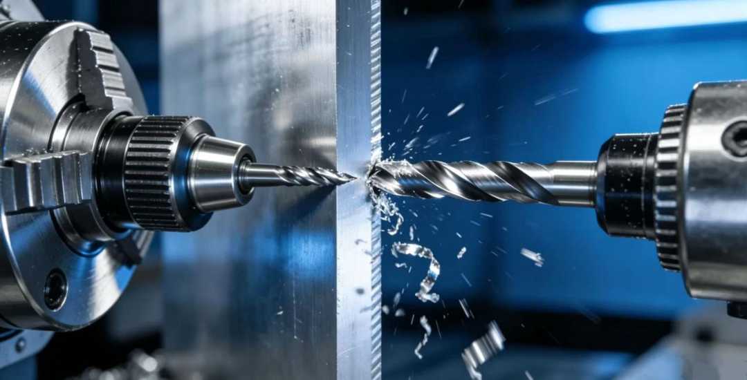
Thin wall machining refers to CNC milling or turning features whose unsupported walls are flexible enough to deflect under cutting forces, clamping pressure, or residual stress during material removal. There is no universal wall thickness that defines a thin wall because stiffness depends on geometry, material, and support conditions rather than thickness alone.
Whether a wall behaves as a thin wall depends on three factors: the height-to-thickness ratio of the unsupported section, the rigidity of the material, and whether ribs or surrounding features provide additional support. A 2 mm wall in 6061 aluminum at a 5:1 ratio behaves very differently from the same wall in 304 stainless steel, even with identical geometry.
Once a wall enters thin-wall territory, the challenge shifts from defining the feature to controlling the machining process. Deflection, chatter, clamping distortion, and residual stress are the four most common causes of dimensional error, and each requires a different machining strategy.
2. Why Thin Walls Deflect, Chatter, and Warp
The height-to-thickness ratio tells you when a wall becomes thin. The next challenge is understanding what causes dimensional error during machining. Deflection, chatter, clamping distortion, and residual stress release each have different root causes, but they often occur together. Solving only one problem rarely produces a stable machining process.
Cutting Force Deflection
Cutting force deflection occurs when radial cutting forces push the wall away from the tool during machining. The wall bends under load and springs back after the tool passes, leaving a tapered or undersized feature. A part may measure correctly while clamped but fall outside tolerance once the cutting forces are removed.
Reducing radial depth of cut is usually the most effective way to minimize deflection. Climb milling helps direct cutting forces into the wall rather than away from it, while backing plates or dedicated supports further improve wall stability before the finish pass.
Vibration and Chatter
Chatter occurs when the cutting frequency approaches the natural frequency of the wall. The wall begins to vibrate, causing the tool to alternate between cutting material and cutting air. The resulting washboard surface is only a symptom; the greater concern is the loss of dimensional accuracy and rapidly deteriorating surface finish.
Adjusting spindle speed is often the quickest way to move the cutting frequency away from resonance. Shortening tool overhang and reducing radial engagement also increase system rigidity and improve machining stability.
Clamping Distortion
Clamping distortion occurs when fixture forces deform the part before machining even begins. Material is removed while the workpiece is held in a distorted shape, and once the clamps are released, the wall springs back to its free-state geometry. Parts that appear accurate in the fixture may therefore fail final inspection.
Distributing clamping forces with soft jaws, vacuum fixtures, or dedicated support features is often more effective than simply increasing clamping pressure. The objective is to hold the part securely without changing its natural shape.
Residual Stress Release
Residual stress release occurs when internal stresses in rolled or extruded stock become unbalanced as material is removed. The part gradually changes shape after roughing or unclamping, a problem commonly seen in high-strength aluminum alloys and stainless steels.
One practical approach is to rough machine the part, remove it from the fixture, allow it to stabilize, and then re-indicate it before the finish pass. For materials with significant residual stress, stress-relief heat treatment before machining or a rough-rest-finish sequence with separate setups is generally more reliable than repeated spring passes.
3. Design Rules: What to Change Before the Part Reaches the Shop
Process changes can reduce thin-wall problems, but good part design prevents many of them before machining even begins. Features such as wall proportions, rib placement, pocket geometry, and realistic tolerances often have a greater impact on machining stability than cutting parameters alone.
Keep the Height-to-Thickness Ratio Under Control
The most effective design rule is to keep the unsupported wall height below approximately eight times the wall thickness. Standard machining is usually sufficient at around a 4:1 ratio, while walls approaching 8:1 often require dedicated machining strategies. Beyond that point, redesigning the part or accepting higher machining cost and risk becomes increasingly likely.
These values are practical design guidelines based on production experience and common CNC machining recommendations rather than fixed industry standards.
Add Ribs Instead of Increasing Wall Thickness
Adding ribs is usually a more efficient way to increase stiffness than simply making the wall thicker. A rib thickness of approximately 50–70% of the main wall is often sufficient, and even a partial rib placed across the longest unsupported span can significantly reduce deflection.
Ribs should improve stiffness without interfering with mating components, fastener access, or moving parts elsewhere in the assembly.
Design Pocket Geometry for Better Stability
Pocket geometry directly affects both tool rigidity and wall stability. Sharp internal corners require smaller end mills, which deflect more easily during cutting. Providing a suitable internal corner radius allows larger, stiffer tools to be used and reduces cutting forces on the wall.
Where possible, avoid making every wall of the same pocket thin. Leaving one side thicker provides additional support throughout machining and reduces the amount of alternate-side finishing required.
Relax Tolerances Where Function Allows
Tight tolerances on thin walls often increase machining cost without improving product performance. Expanding a tolerance from ±0.01 mm to ±0.05 mm may have little effect on function while significantly improving manufacturability and reducing scrap.
Specify the loosest tolerance that satisfies the functional requirements rather than the tightest tolerance the machine is capable of producing.
4. Workholding: Keeping the Wall in Position
Thin-wall workholding focuses on distributing clamping force evenly so the part maintains its free-state geometry throughout machining. Increasing clamping force rarely improves stability and often introduces additional distortion.
Soft jaws distribute clamping pressure across a larger contact area, while vacuum fixtures are well suited to parts with large, flat back faces because they eliminate localized loading. When unsupported walls become too tall, temporary backing material can be added behind the wall during machining and removed once the operation is complete.
For thin cylindrical components, soft jaws or segmented collets are usually preferred over standard three-jaw chucks. A conventional three-jaw chuck can distort a thin ring before machining even begins, making it difficult to achieve accurate free-state dimensions.
At Beska, workholding is evaluated before cutting parameters are finalized. One of the first checks is whether the part will measure the same in the fixture as it does after unclamping. If not, the clamping strategy is revised before machining begins.
After machining, critical dimensions should always be verified in the free state without fixturing force. If dimensional changes appear only after unclamping, the primary source of error is usually the workholding method rather than the cutting process itself.
5. Tool Selection and Cutting Strategy
Thin-wall machining is fundamentally a force-control problem. Tool selection, cutting parameters, and toolpath strategy must work together to remove material while keeping cutting forces low enough to prevent wall deflection. Optimizing only one of these factors rarely produces stable machining results.
Tool Selection: Sharp, Short, and Stiff
Sharp carbide tools with positive rake angles reduce the cutting forces acting on the wall. For aluminum, high-helix end mills with polished flutes are commonly used to improve chip evacuation and reduce cutting resistance.
Whenever geometry allows, use the largest practical tool with the shortest possible overhang. Smaller tools should be selected only when required by the feature geometry, with lighter radial engagement to compensate for the reduced rigidity.
Cutting Parameters: Controlling Cutting Forces
Radial depth of cut has the greatest influence on wall deflection. As the wall approaches its final thickness, radial engagement is typically reduced to approximately 10–15% of the tool diameter to minimize side loading.
Light radial engagement should be combined with higher spindle speeds and lower feed per tooth. These values are practical starting points and should be adjusted according to the material, tool condition, and machine rigidity. Before the final finishing pass, a trial cut on a representative feature is often worthwhile to verify machining stability.
Finishing Strategy: Alternate Sides, Step Down in Layers
Alternate-side finishing helps balance cutting forces by removing material from opposite sides in sequence rather than continuously loading one wall. For tall walls, machining in multiple axial layers instead of profiling the full height in a single pass further improves dimensional stability.
Effective chip evacuation is equally important. Packed chips increase friction, raise cutting temperature, and damage the finished surface. Through-tool coolant or air blast is commonly used for aluminum, while dry machining with air blast is often preferred for most plastics.
6. Material Selection for Thin Walls: Aluminum, Steel, Titanium, and Plastics
Material selection largely determines how aggressively a thin wall can be machined before stability becomes a problem. Stiffness, cutting force, thermal behavior, and residual stress all influence the practical limit of wall thickness, so different materials require different machining strategies.
Aluminum
6061-T6 is the preferred material for thin-wall machining because it combines good stiffness, low cutting forces, and relatively low residual stress. Walls below 1 mm are routinely achievable with an appropriate machining strategy. 7075 offers higher strength but also contains greater residual stress, making stress-relieved stock a better choice for demanding thin-wall applications.
Stainless Steel
Compared with aluminum, 304 and 316 stainless steels generate higher cutting forces and tend to work-harden, making wall deflection more difficult to control. Wall thicknesses of around 1 mm are generally practical, provided radial engagement is kept low and finish tools remain sharp. Replacing worn tools is often more economical than correcting dimensional errors caused by work hardening.
Titanium
Titanium combines high strength with low thermal conductivity and relatively low stiffness, allowing walls to deflect easily while concentrating heat at the cutting edge. In most production environments, wall thicknesses of approximately 1.5 mm or greater provide a more stable starting point. Careful control of tooling, coolant, and cutting parameters is essential.
Plastics
Unlike metals, thin plastic walls are more likely to deform from heat than from cutting force. Materials such as POM and nylon machine well with sharp tools, consistent chip load, and effective air blast cooling. Excessive rubbing quickly softens the material and reduces dimensional accuracy.
No material has a fixed minimum wall thickness. The practical limit depends on how the material behaves during machining. Aluminum generally provides the widest machining window, while titanium demands much tighter control of tooling, workholding, and cutting parameters to maintain dimensional stability.
7. Real-World Thin Wall Machining Examples
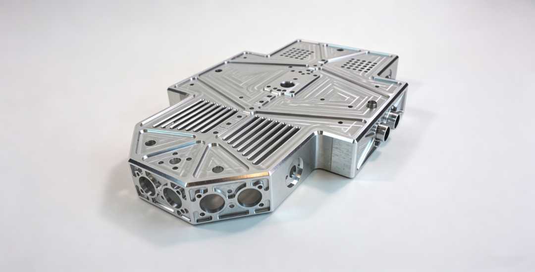
The same design rules apply differently depending on the material, geometry, and service requirements. The following examples show how the machining strategy changes to control the dominant source of error.
| Application | Main Challenge | Key Solution |
| Electronics enclosure | Wall deflection | Alternate-side finishing, soft jaws, support ribs |
| Aerospace bracket | Residual stress | Stress-relieved stock, rough-rest-finish sequence |
| Medical housing | Work hardening | Sharp tooling, low radial engagement |
Electronics Enclosure with Internal Pocket Walls
Tall internal pocket walls in a 6061 aluminum enclosure tend to deflect during pocket milling, leaving tapered walls after finishing. Alternate-side contour finishing, profile-matched soft jaws, and a support rib across the longest unsupported span significantly improve wall stability and reduce the number of finish passes.
Aerospace Bracket with Thin Web Sections
Thin web sections in a 7075 aerospace bracket are highly sensitive to residual stress after unclamping. Using stress-relieved stock together with a rough-rest-finish sequence produces much more stable dimensions than machining directly to size in a single setup.
Stainless Steel Medical Device Housing
Thin 316L medical housings are affected more by work hardening than wall stiffness alone. Keeping finish tools sharp through scheduled replacement and using low radial engagement helps maintain dimensional accuracy and surface quality.
Although the applications differ, the engineering principle remains the same: once a wall becomes flexible, material selection, workholding, tooling, and machining sequence all become equally important to achieving stable results.
8. When Thin Walls Are the Wrong Specification
Thin walls are not always the best engineering solution. In many applications, increasing wall thickness improves manufacturability, reduces cost, and delivers the same functional performance.
Weight Reduction Is Not Functionally Required
If weight is not a design requirement, increasing wall thickness is often the simplest and most economical solution. A slightly thicker wall improves rigidity, reduces machining risk, and lowers scrap without affecting the part’s intended function.
Tight Tolerances Exceed Practical Machining Limits
Thin walls are difficult to machine within very tight tolerances because they deflect easily during cutting and clamping. If the application allows, relaxing the tolerance often makes the design significantly easier and more economical to manufacture.
Production Volume Does Not Justify the Process
Thin-wall machining frequently requires dedicated soft jaws, vacuum fixtures, and multiple finishing operations. For prototype or very low-volume production, these additional setups may not be cost-effective. In some cases, a thicker machined wall or an alternative manufacturing process provides better overall value.
High Cutting Forces Are Unavoidable
Some machining operations require relatively high cutting forces to achieve the desired geometry or surface finish. If the wall cannot withstand those forces without excessive deflection, increasing wall thickness is usually a more reliable solution than trying to compensate through process adjustments alone.
Wall thickness should always be determined by function rather than appearance. A part should be only as thin as necessary to meet its weight, strength, tolerance, and manufacturing requirements.
Conclusion
Thin-wall machining is not defined by wall thickness alone. Successful results depend on balancing part geometry, material selection, workholding, tooling, and cutting strategy so the wall remains stable throughout the machining process. Considering these factors during the design stage is often the most effective way to improve dimensional accuracy, reduce scrap, and control machining cost.
At Beska, thin-wall machining is planned during the DFM stage rather than corrected on the shop floor. Our engineering team reviews wall geometry, material selection, workholding, tooling, and machining sequence before production to improve stability and achieve consistent results for precision CNC machined parts. If your design includes thin-wall features, we can help identify potential machining risks and recommend practical manufacturing solutions before production begins.
 English
 Hebrew
 Turkish
 French
 Russian
 German
 Spanish
 Portuguese