


Materials in engineering are often judged by two key characteristics: stiffness and strength. While they may seem similar, confusing them can lead to serious design errors. Many engineers, especially those new to the field, assume that a “hard” material is automatically strong or that a material that resists bending or stretching will also resist breaking.
In reality, stiffness and strength describe different physical behaviors of materials under load. Stiffness determines how much a structure deforms under a given force, while strength determines the maximum load it can withstand before failing.
This article will explore the definitions, testing methods, and practical applications of stiffness and strength, highlight common misconceptions, and provide guidance on how engineers prioritize these properties in real-world designs.
1. What is Stiffness?
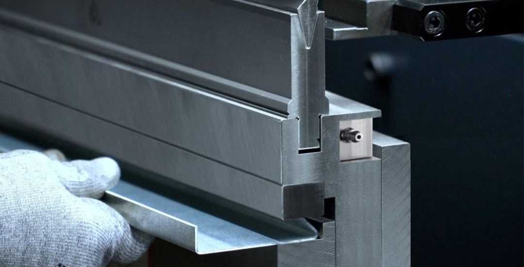
Stiffness describes a material or structure’s ability to resist elastic deformation under load. In other words, it answers the question, “How much does this object deform when a force is applied?” Stiffness is determined by both the atomic bonding forces within the material and the geometry of the structure. Its primary metric is the elastic modulus (E), an inherent material property. At the structural level, stiffness also depends on the cross-sectional moment of inertia (I), the length (L), and the support conditions of the component.
In engineering practice, stiffness is crucial for precision, stability, vibration control, and comfort. Examples include machine tool beds that must maintain alignment during cutting, bridges that minimize deflection under traffic loads, and vehicle chassis designed to reduce vibration. Insufficient stiffness can lead to loss of accuracy, excessive vibrations, sticking mechanisms, or seal failures, even if the material’s strength is sufficient.
2. What is Strength?
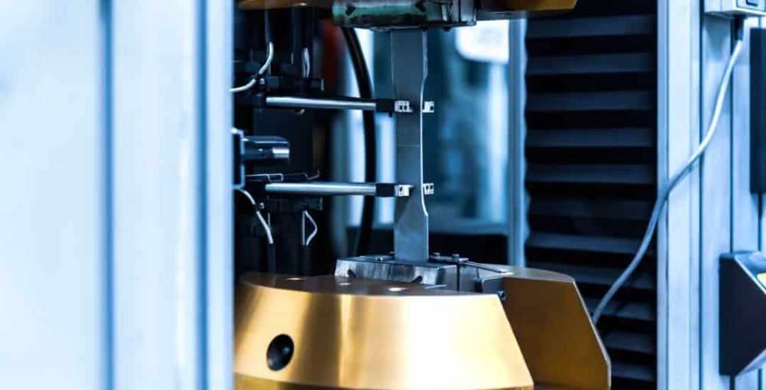
Strength indicates a material or structure’s ability to withstand loads without failure, including yielding, plastic deformation, fracture, or buckling. Key indicators include yield strength (Rp0.2), tensile strength (Rm), compressive strength, and fatigue strength. These properties are influenced by dislocation movement, grain boundaries, phase structures, and material defects.
Strength is essential for ensuring safety, load-bearing capacity, and durability. For example, shafts must resist torsion without breaking, gears must transmit torque without shearing, and pressure vessels must endure internal pressure safely. A structure that meets stiffness requirements but lacks sufficient strength is at risk of catastrophic failure.
3. Key Comparison: Stiffness vs Strength
After understanding each concept individually, it is useful to see how they differ in practice. The following table summarizes the key aspects engineers consider when evaluating stiffness and strength:
| Aspecto | Stiffness | Força |
| Design goal | Control elastic deformation, deflection, rotation | Prevent yielding, fracture, buckling, fatigue |
| Material property | Elastic modulus E (largely unaffected by heat treatment) | Yield/tensile strength (can be significantly enhanced by heat treatment) |
| Structural influence | Sensitive to cross-section shape, length, and support | Sensitive to cross-sectional area and stress distribution |
| Design keywords | Deflection limits, slenderness ratio, rigidity ratio | Safety factor, allowable stress, fatigue life |
| Failure consequence | Loss of precision, vibration, sticking, seal failure | Fracture, collapse, explosion, safety hazards |
| Typical scenarios | Machine tools, guideways, vehicle chassis, precision frames | Lifting cables, crankshafts, pressure vessels, main bridge beams |
In summary, stiffness determines how much a component deforms under load, directly affecting precision and usability, while strength defines the material’s capacity to withstand failure, ensuring safety and reliability.
4. Methods for Measuring Stiffness and Strength
Engineers measure stiffness and strength through standardized laboratory tests that apply controlled loads and record how materials deform or fail.
Ensaio de Tração
The tensile test is the most common method for evaluating mechanical properties. A specimen is placed in a universal testing machine and pulled until deformation and fracture occur. The recorded force and elongation are converted into a stress–strain curve.
From this test, engineers can determine:
- Elastic modulus (E) from the slope of the linear region, representing stiffness
- Yield strength, where permanent deformation begins
- Ultimate tensile strength, the maximum stress before fracture
An extensometer is often used to measure small elastic deformations with higher accuracy.
Bending Test
Bending tests, such as three-point or four-point setups, are widely used for plates, beams, and brittle materials. By measuring load and deflection, engineers can evaluate:
- Bending stiffness, which controls deflection under load
- Bending strength, which indicates the stress level at failure
Dynamic Testing (Modal Analysis)
For structures where vibration performance matters, engineers may perform modal analysis. The structure is excited using an impact hammer or shaker, and sensors record vibration responses. Natural frequencies obtained from the test help estimate structural stiffness and dynamic behavior.
Together, these testing methods help engineers evaluate how materials deform, carry loads, and ultimately fail in real applications.
5. Stress-Strain Curves: The Visual Language of Mechanics
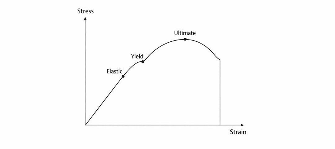
One of the clearest ways to see the difference between stiffness and strength is through the stress–strain curve obtained in a tensile test. This curve shows how a material responds as load increases and deformation begins to develop.
In a typical stress–strain diagram:
- The horizontal axis (strain) represents the amount of deformation relative to the original length.
- The vertical axis (stress) represents the force applied per unit area.
Several key points on this curve describe the mechanical behavior of a material.
- Elastic region: At the beginning of the curve, stress and strain increase proportionally. The slope of this straight section is the elastic modulus (E). A steeper slope indicates greater stiffness, meaning the material resists deformation more effectively.
- Yield point: When the curve starts to bend away from the straight line, the material begins to deform plastically. The stress at this transition is known as the yield strength.
- Ultimate tensile strength: The highest point on the curve represents the maximum stress the material can sustain before fracture begins.
This curve also explains why materials with very different strengths can still have similar stiffness. For example, two steels with different heat treatments often show nearly the same elastic slope, while their yield and tensile strengths differ greatly.
6. Comparing Material Performance: Stiffness and Strength
Different materials show very different combinations of stiffness and strength. The table below lists several commonly used engineering materials and compares their elastic modulus, strength levels, and density to provide a clearer perspective.
| Material | Grade/Condition | Elastic Modulus (GPa) | Yield Strength (MPa) | Tensile Strength (MPa) | Densidade (g/cm³) | Notas |
| Low Carbon Steel | Q235 / A36 | 200–210 | 235 | 370–500 | 7.85 | Moderate stiffness, low strength, easy to machine, low cost |
| High Strength Steel | 42CrMo (quenched & tempered) | 200–210 | 930 | 1080 | 7.85 | Same stiffness as low carbon steel, ~4x strength |
| Aluminum Alloy | 6061-T6 | 69 | 276 | 310 | 2.7 | 1/3 stiffness of steel but high strength-to-weight ratio |
| Titanium Alloy | Ti-6Al-4V | 110 | 880 | 950 | 4.43 | Medium stiffness, high strength, corrosion resistant, expensive |
| Fibra de carbono | T800 / Epoxy | 140–160* | 1500+ | 2500+ | 1.6 | Anisotropic, extremely high stiffness and strength along fibers |
*Note: Stiffness is generally less affected by processing compared to strength.
From this comparison, one pattern becomes clear. Strength can vary dramatically within the same material family, while stiffness tends to remain relatively stable.
7. Common Misconceptions in Engineering
When comparing stiffness and strength, it’s easy to get the two confused. Some materials behave in ways that can seem counterintuitive, and overlooking this can lead to design issues.
Stiffness does not equal strength
A high-strength carbon fiber rod can carry a large load without breaking, yet it may bend more than a steel rod. High strength doesn’t automatically mean high stiffness.
Harder is not always better
Materials that resist surface wear may still be brittle. Diamond, for example, is extremely hard but can fracture under impact.
Usability versus safety
In precision equipment, stiffness often matters more than absolute strength. A CNC guideway might bend just enough to disrupt function, even if the stress never reaches the material’s yield point.
These examples show clearly that stiffness and strength serve different roles: one controls how a structure deforms, while the other determines how much load it can safely bear.
8. Balancing Strength and Stiffness in Design
In engineering design, balancing strength and stiffness is essential, and the order of priority depends on the structure’s function and precision requirements.
Start with strength
The first consideration is usually safety. Components must withstand expected loads without yielding, fracturing, or failing. This sets the minimum dimensions or material requirements for the design.
Check stiffness next
After strength is ensured, the part is evaluated for stiffness. It must resist excessive deflection or twist under operational loads. If the deformation exceeds acceptable limits, adjustments are made to the cross-section or geometry to improve rigidity.
Example: Shaft design
A shaft transmitting torque illustrates this process: the minimum diameter is first calculated to satisfy strength requirements. Then deflection and twist are checked under load. If the shaft is too flexible, the diameter or cross-sectional shape is increased to meet stiffness needs.
Precision-critical structures
For highly sensitive systems such as space telescope frames or optical assemblies, stiffness can dominate the design. Even when strength is sufficient, dimensions may be controlled primarily to limit deformation and maintain functionality.
Strength ensures a component survives, while stiffness ensures it performs as intended. A practical design balances both, giving safety and usability equal attention.
Conclusão
Stiffness determines how a structure maintains its shape and function, while strength ensures it can safely carry loads. Together, they form the foundation for reliable and precise engineering design.
Advanced material combinations, such as stainless steel tubes paired with ultra-high-performance concrete, illustrate how engineers can balance deformation and safety in modern structures.
For components where precision and reliability are critical, consult a skilled precision machining supplier like the Beska team is key to turning these design principles into high-quality, functional parts.
Deeper into Our Resources
For some insightful reads, we’ve curated a list of recommended articles just for you:
 Portuguese
 English
 Hebrew
 Turkish
 French
 Russian
 German
 Spanish