


In a robotic system, the performance of the whole machine often depends on a few critical mechanical parts. A misselected material or an unnecessarily tight tolerance on a single arm link can create repeat positioning errors, premature joint wear, and unnecessary machining cost.
This article focuses on the mechanical components commonly used in robotic systems, including material selection, manufacturing methods, and DFM considerations. The emphasis is on practical manufacturing decisions that influence accuracy, durability, and production efficiency.
1. Core Mechanical Part Categories in Robotic Systems
Robotic systems contain many different mechanical components, but they do not place the same demands on manufacturing. An arm link, a transmission shaft, and a gripper jaw may all belong to the same robot, yet their material selection, machining process, and tolerance requirements are completely different.
Structural Frames and Arm Links
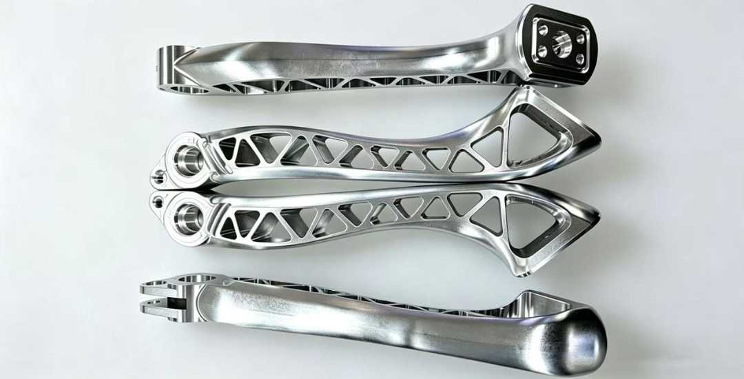
Structural frames and arm links form the main body of articulated robots, SCARA robots, and delta systems. These components are designed to remain lightweight while maintaining sufficient stiffness under repeated acceleration and deceleration. Aluminum alloys are widely used, but thin-wall structures are prone to machining deformation. Wall thickness, rib design, and workholding often have a greater influence on final accuracy than material strength alone.
Joint Shafts and Hubs
Joint shafts and hubs transfer rotary motion between motors, gear reducers, and robotic arms. Bearing journals, spline interfaces, and runout control usually determine the machining strategy. Wear-critical surfaces are often heat treated and finish ground to maintain dimensional accuracy and long-term reliability.
Transmission and Gear Components
Gears, timing pulleys, and spline connections transmit motion and torque throughout the robot. These components require accurate tooth geometry, controlled surface finish, and consistent hardness. Heat treatment and machining accuracy both influence backlash, transmission efficiency, and service life.
End Effector Interface Parts
Gripper jaws, tool changers, and mounting plates connect the robot arm to end-of-arm tooling. Material and design requirements vary by application. Automation equipment may prioritize wear resistance and gripping force, while semiconductor and medical systems often require low particle generation, corrosion resistance, or electrical insulation.
Mounting and Fastening Hardware
Base brackets, adapter plates, locating features, and precision fasteners support the robot structure and maintain alignment during operation. Flatness, hole position, and assembly tolerances often have a greater impact on installation accuracy than surface finish alone, particularly on large structural components.
Although these components serve different functions, they share the same objective: maintaining positioning accuracy, structural rigidity, and long-term reliability throughout the robot’s service life. Those requirements ultimately determine the choice of materials, manufacturing processes, and inspection methods used during production.
2. How Robotic Mechanical Parts Are Manufactured
Robotic mechanical parts can be manufactured using several different processes, and the best choice depends on production volume, required accuracy, part geometry, and product maturity. A prototype arm link and a high-volume gearbox housing may serve similar functions, but their manufacturing methods can be completely different. Selecting an appropriate process early helps balance machining cost, lead time, and production consistency.
CNC Machining for Prototypes and Low-to-Mid Volume Production
CNC milling and turning remain the primary manufacturing methods for robotic mechanical parts, especially during product development and low-to-mid volume production. They support everything from one-off prototypes to several hundred parts without requiring dedicated tooling.
For most robotic component projects we manufacture, production volumes range from a few pieces to several hundred units. Usinagem CNC provides the flexibility to modify designs between batches while maintaining consistent dimensional accuracy. Multi-axis machining is commonly used for complex geometries, while standard 3-axis machining remains a cost-effective solution for many structural components.
Precision Finishing for Motion-Critical Features
Certain robotic components require tighter control than standard machining can provide. Bearing seats, drive shafts, gear interfaces, and other motion-critical features often undergo finish grinding after heat treatment or rough machining to improve dimensional accuracy, runout, and surface finish.
Manufacturing for High-Volume Production
When product designs become stable and production volumes increase, dedicated manufacturing processes often become more economical. Aluminum structural components may be produced by die casting, while plastic covers, cable guides, and other non-structural parts are commonly manufactured through injection molding. Although these processes require significant tooling investment, they can substantially reduce the cost per part in large production runs.
Rapid Prototyping for Early Design Validation
During the early development stage, additive manufacturing methods such as selective laser sintering (SLS) are often used to verify form, fit, and assembly before machining production parts. When functional testing requires production materials or tighter tolerances, CNC machining remains the preferred option.
The table below summarizes the manufacturing methods commonly used for robotic mechanical parts and the situations where each process is most appropriate.
| Manufacturing Process | Typical Volume Range | Typical Dimensional Accuracy | Tempo de espera | Typical Robotic Applications |
| CNC Machining (Milling / Turning) | 1–500 pcs | ±0.02–0.05 mm | 1–2 weeks | Structural links, joint housings, custom brackets, mid-volume structural parts |
| Precision Grinding | 10–1,000 pcs (post-process) | ±0.002–0.01 mm | 2–3 weeks | Drive shafts, bearing bores, gear mating surfaces, motion-critical features |
| Die Casting (Aluminum) | >5,000 pcs | ±0.05–0.08 mm | 5–7 weeks (including tooling) | High-volume joint housings, base frames, aluminum structural parts |
| Injection Molding (Plastic) | >10,000 pcs | ±0.05–0.1 mm | 4–6 weeks (including tooling) | Plastic enclosures, cable brackets, lightweight non-structural components |
| Prototipagem Rápida SLS | 1–10 pcs | ±0.1–0.2 mm | 1–3 days | Design validation, assembly verification, concept prototypes |
3. Choosing Materials for Robotic Components
Robotic mechanical parts rarely use a single material throughout the entire system. Structural components, transmission parts, end effectors, and insulating parts operate under different loading conditions, so material selection is usually based on the function of each component rather than maximizing a single material property.
| Material Category | Common Grade | Relação Força-Peso | Usinabilidade | Estabilidade Dimensional | Relative Cost | Typical Use Case |
| Wrought Aluminum | 6061-T6 | Moderate-High | Excelente | Good with stress relief | Low-Medium | Arm links, frames, mounting plates |
| High-Strength Aluminum | 7075-T6 | Alto | Bom | Moderado | Médio | High-load arm segments, end effector bodies |
| Liga de aço | 4140 HT | Muito alto | Fair | Good with post-processing | Médio | Shafts, gears, splined hubs |
| Aço inoxidável | 304 / 303 | Moderado | Fair | Very Good | Medium-High | Cleanroom parts, corrosion-resistant brackets |
| Unfilled Engineering Plastic | POM | Low-Moderate | Excelente | Temperature-sensitive | Baixo | Low-load gears, bearing seats |
| Glass-Filled Plastic | GF30 PEEK | Moderate-High | Fair | Bom | Alto | End effector jaws, insulating components |
| Carbon Fiber Composite | Prepreg Laminate | Excelente | Poor secondary machining only | Excelente | Muito alto | High-performance arm links, delta frames |
Sources: MatWeb material property database and manufacturer technical datasheets. Actual performance varies with material grade, heat treatment, geometry, and manufacturing process.
Ligas de alumínio are widely used for structural components because they reduce moving mass while maintaining good stiffness. Steel is commonly selected for shafts, gears, and other wear-critical components that require higher strength and fatigue resistance. Engineering plastics and composite materials are typically used where electrical insulation, corrosion resistance, or weight reduction is more important than maximum mechanical strength. In practice, robotic systems often combine several materials, with each selected according to the function of the component rather than applying a single material throughout the assembly.
4. DFM Design Considerations for Robotic Parts
Robotic mechanical parts often combine lightweight structures, precision features, and complex geometries. Small design decisions made before machining can reduce deformation, simplify fixturing, shorten production time, and improve assembly consistency. The following considerations have the greatest impact on manufacturability.
Lightweight Design Without Sacrificing Stiffness
Reducing moving mass improves robot acceleration and lowers motor load, but excessive material removal can reduce rigidity and increase machining deformation. Thin walls, large pockets, and unsupported features are more likely to deflect during machining. Internal ribs are often a more effective way to increase stiffness than simply increasing wall thickness, provided they do not restrict tool access.
Tolerance Allocation
Not every feature requires precision-level tolerances. Bearing seats, joint interfaces, locating features, and mating surfaces should receive tighter control, while non-critical holes and cosmetic surfaces can usually be machined to standard CNC tolerances. Tolerances should be determined by functional requirements rather than the maximum capability of the machine, helping reduce machining time and inspection cost.
Machining and Fixturing
Part geometry directly affects machining stability. Deep narrow pockets, long unsupported walls, and features that require excessive tool overhang increase vibration and reduce surface quality. Wherever possible, include flat and parallel clamping surfaces that allow secure workholding with standard fixtures, especially for prototype and low-volume production.
Material-Specific Considerations
Different materials often require different machining strategies. Aluminum components with high material removal rates may benefit from stress relief between rough and finish machining. Heat-treated steel parts usually require additional machining allowance for final grinding or finishing, while engineering plastics require sharp cutting tools and controlled cutting parameters to minimize heat buildup and deformation.
Assembly and Serviceability
Features that simplify assembly can reduce production time and improve consistency. Chamfers on shaft ends, pilot features for locating parts, and adjustable mounting slots all help reduce alignment time during assembly and minimize the risk of installation damage. These small design details often have a greater impact on manufacturing efficiency than they first appear.
5. Manufacturing Examples from Robotic Components
The following examples show how design, material selection, and manufacturing decisions come together in actual robotic components. Rather than relying on a single machining technique or material, successful production often depends on selecting the right process sequence to control deformation, maintain accuracy, and simplify assembly.
6-Axis Robot Upper Arm Link
This lightweight structural component was designed to reduce moving mass while maintaining sufficient stiffness under repeated acceleration. The thin-wall geometry made machining deformation the primary challenge rather than material strength.
To improve dimensional stability, both sides of the part were rough machined before finishing. Form-fitting soft jaws distributed clamping force more evenly, while light finishing cuts minimized cutting forces during the final operation. This machining sequence reduced deformation and produced more consistent wall thickness without increasing production time.
Joint Drive Splined Shaft
This shaft transfers torque from the gear reducer to the robot joint and requires accurate bearing fits together with durable spline surfaces. Surface hardening improved wear resistance, but heat treatment introduced dimensional changes that affected runout and assembly accuracy.
Instead of attempting to hold the final dimensions before heat treatment, additional machining allowance was reserved on the bearing journals and spline diameters. After hardening, the critical surfaces were finish ground to restore dimensional accuracy and concentricity, allowing the shaft to assemble without secondary fitting.
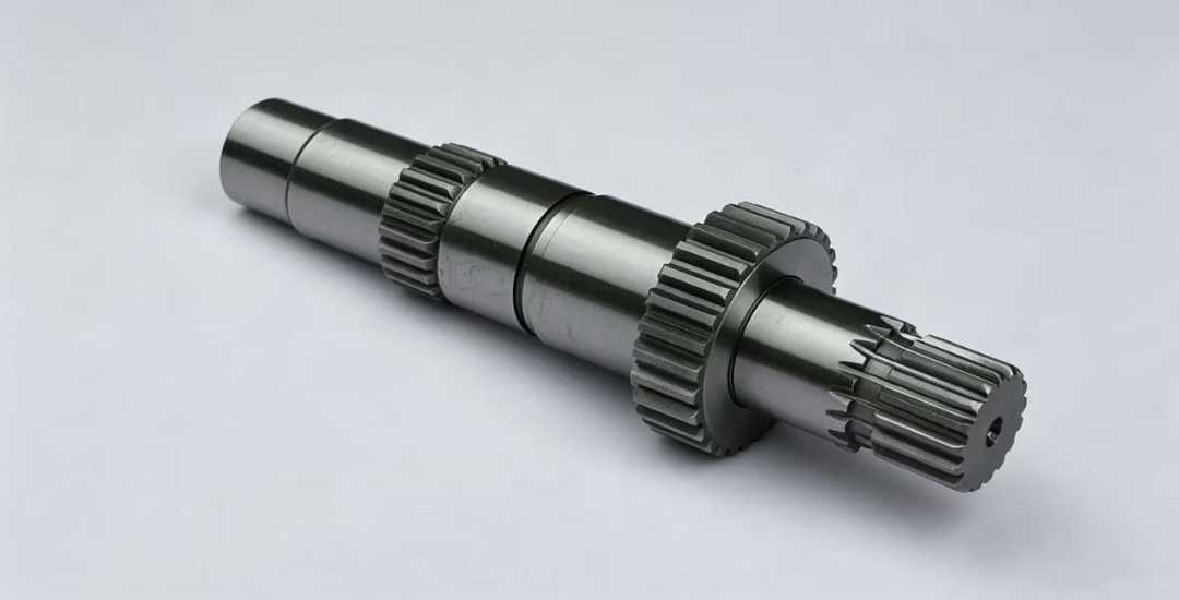
These two examples represent two common manufacturing priorities in robotic mechanical parts. Structural components often focus on controlling deformation while reducing weight, whereas transmission components place greater emphasis on dimensional stability, wear resistance, and post-heat-treatment accuracy. Although the manufacturing methods differ, both cases demonstrate the importance of matching the machining process to the function of the part.
6. Common Production Challenges for Robotic Mechanical Parts
Robotic mechanical parts often combine lightweight structures, precision motion systems, and complex geometries. The following production challenges are among the most common and are usually easier to address during design than after machining begins.
Machining Deformation
Thin-wall structures and large pockets can deform during machining, particularly on lightweight aluminum components. Stable workholding, balanced machining sequences, and appropriate clamping force help improve dimensional consistency.
Heat Treatment Distortion
Heat treatment improves wear resistance but can affect runout and critical dimensions on shafts and transmission components. Leaving finish machining allowance before heat treatment and grinding critical surfaces afterward is a common approach to restoring dimensional accuracy.
Assembly Accuracy
Small deviations in hole position, flatness, or concentricity can accumulate during assembly and reduce positioning accuracy. Inspection should focus on functional interfaces rather than applying unnecessarily tight tolerances throughout the entire part.
Material-Specific Challenges
Different materials require different machining strategies. Engineering plastics may develop residual stress during machining, while carbon fiber composites are prone to edge delamination if improper tooling or cutting parameters are used.
Conclusão
Robotic mechanical parts place different demands on materials, machining, and dimensional control. Matching the manufacturing approach to the function of each component is often more important than applying the same design rules across an entire assembly.
At Beska, we work with engineering teams to review robotic parts before production, helping identify practical improvements in material selection, machining strategy, tolerance allocation, and manufacturability.
 Portuguese
 English
 Hebrew
 Turkish
 French
 Russian
 German
 Spanish