


UM sheet metal part can look completely workable in CAD and still become difficult to cut, bend, weld, or assemble. Small decisions such as placing a hole too close to a bend, choosing an unsuitable bend radius, or applying an unnecessarily tight tolerance can create problems once the flat blank reaches the shop floor.
Unlike a machined part, sheet metal changes shape during forming. The material stretches and compresses through a bend, springs back after the load is released, and may distort further during welding. CAD models can account for these effects only when the material, bend allowance, tooling, and process assumptions match the actual fabrication conditions.
Many of these problems can be reduced through relatively small design changes made before production. The following sections look at ten common sheet metal design mistakes, why they create manufacturing problems, and how they can be adjusted during DFM review.
1. Placing Holes and Features Too Close to Bend Zones
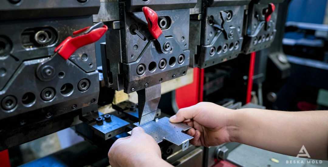
Holes, slots, cutouts, and other features placed too close to a bend can distort during forming. A round hole may become slightly oval, a slot may shift, or a feature intended for a fastener or connector may no longer align correctly after bending.
The reason is that material around the bend does not remain dimensionally unchanged. The outside of the bend is stretched while the inside is compressed, and nearby features can be pulled into this deformation zone. The closer a feature is to the bend, the more its final geometry may depend on the material, bend radius, and forming method.
There is no single clearance value that works for every sheet metal part. The required distance depends on material type and temper, sheet thickness, inside bend radius, die opening, tooling, and the type of feature being formed nearby.
DFM Optimization Tip: Check holes, slots, threads, and cutouts near every bend during design review. Where possible, move critical features outside the bend-affected zone. If the feature must remain close to the bend, confirm the required clearance or relief with the fabricator based on the actual material and tooling.
2. Choosing a Bend Radius That Does Not Match the Material and Tooling
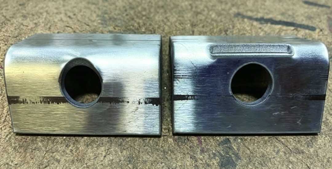
The inside bend radius affects how much strain develops on the outer surface of the sheet during forming. If the specified radius is too small for the selected material and condition, the bend may crack or show visible surface damage.
There is no single minimum bend radius that applies to all steels, stainless steels, or aluminum alloys. Bendability depends on the material grade and temper, sheet thickness, rolling direction, bend angle, forming method, and available tooling. A radius that works well for one aluminum alloy may be unsuitable for another alloy in the same thickness.
The bend radius also affects bend allowance, springback, and the tooling required to form the part. Using several different radii on one component may require additional press-brake setups, while a consistent radius can simplify production when the functional requirements allow it.
DFM Optimization Tip: Select the bend radius based on the actual material grade, temper, thickness, and forming process rather than applying one thickness ratio to every part. Where practical, use consistent bend radii across the component and confirm unusually tight bends with the fabricator before production.
3. Omitting Bend or Corner Relief Where It Is Needed
Bend reliefs are small cutouts placed near the end of a bend to give the material room to deform during forming. They are especially useful where a bend terminates close to an edge, cutout, or adjacent flange.
Without sufficient relief, material near the corner may be pulled or compressed into a confined area as the flange is formed. This can lead to tearing, bulging, local distortion, or an uneven corner that affects fit and appearance.
The required relief geometry is not the same for every part. Its width, length, and shape depend on the sheet thickness, bend radius, material, corner geometry, and forming method. In some designs, the surrounding geometry already provides enough clearance and no additional relief is needed.
DFM Optimization Tip: Review the ends of bend lines and intersecting flanges for restricted material movement. Add bend or corner relief where needed, and size it according to the actual material, bend radius, and tooling rather than applying one fixed rule to every sheet metal part.
4. Ignoring Springback During Bend Design
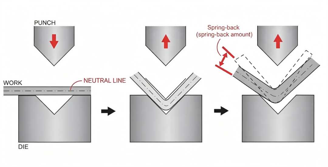
After a sheet metal bend is formed and the load is released, the material tends to recover part of its elastic deformation. This springback causes the final bend angle or radius to differ from the shape produced while the tooling is under load.
The amount of springback is not fixed. It depends on the material grade and condition, yield strength, elastic modulus, sheet thickness, bend-radius-to-thickness ratio, bend method, and tooling geometry. Higher-strength materials generally require more compensation, but the actual result must be determined for the specific material and forming setup.
Springback can be compensated through overbending, press-brake angle correction, tooling selection, or other forming strategies. Production parts may also require test bends or process validation when angle accuracy is important.
Bend allowance and bend deduction should not be confused with springback compensation. The first determines the flat pattern dimensions, while springback compensation helps achieve the required final bend angle after forming.
DFM Optimization Tip: Define critical bend angles clearly and avoid assuming that the programmed or nominal forming angle will equal the released part angle. Confirm springback-sensitive bends using the actual material, thickness, tooling, and forming process.
5. Specifying Tolerances That Do Not Match Sheet Metal Fabrication
Sheet metal parts pass through several different processes, such as cutting, bending, welding, and assembly. Each operation introduces its own variation, so dimensions on a formed part do not behave the same way as dimensions produced directly by CNC machining.
Tolerances that are practical for a laser-cut feature may be difficult to maintain after several bends or a welded assembly. Formed dimensions can also depend on material thickness, bend radius, tooling, springback, datum selection, and the sequence in which the part is fabricated.
Applying the same tight tolerance to every dimension can increase inspection effort and may require additional process control, secondary machining, straightening, or special fixturing. These extra steps are often unnecessary when the dimension does not affect fit, function, sealing, or assembly.
DFM Optimization Tip: Apply tighter tolerances only to function-critical features and dimensions. Use practical general tolerances elsewhere, and review especially tight requirements with the fabricator to confirm whether they can be achieved through normal sheet metal processing or require a secondary operation.
6. Placing Holes, Slots, or Hardware Too Close to an Edge
Holes, slots, and other cut features placed very close to a sheet edge can leave only a narrow strip of material between the feature and the part boundary. Depending on the geometry and process, this narrow section may distort during cutting or forming, or provide insufficient strength for the intended load.
The required edge distance is not the same for every feature. A clearance that is acceptable for a simple laser-cut hole may not be sufficient for a loaded fastener, a slotted feature, or self-clinching hardware. Pressed-in nuts, studs, and similar components also have their own minimum edge-distance requirements based on the specific fastener and sheet thickness.
Narrow webs can also become more sensitive to heat, forming forces, or local deformation during secondary operations. For this reason, edge distance should be evaluated together with the material, sheet thickness, feature size, manufacturing process, and functional load.
DFM Optimization Tip: Avoid applying one universal edge-distance ratio to every hole or slot. Check narrow webs for cutting and forming stability, and use the hardware manufacturer’s specified edge-distance requirements when self-clinching or other installed fasteners are involved.
7. Ignoring Rolling Direction in Bend Design
Rolling can give sheet metal direction-dependent mechanical properties, so the orientation of a bend relative to the rolling direction can affect formability. For some alloys and higher-strength materials, a bend that is acceptable in one orientation may require a larger radius in another.
The effect depends on the material grade, temper or condition, sheet thickness, and required bend radius. Some materials tolerate tighter bends when the bend is oriented in a particular direction relative to rolling, while others follow different recommendations. For this reason, one bend orientation should not be treated as a universal rule for all sheet metals.
Rolling direction becomes especially important when the design combines a relatively tight bend with a material that has limited ductility. In these cases, ignoring orientation can increase the risk of cracking or force the manufacturer to use a larger bend radius.
DFM Optimization Tip: Check the material supplier’s bendability data when rolling direction may affect a critical bend. Specify the required orientation on the drawing when it is functionally important, and confirm that the sheet nesting and fabrication process can maintain that orientation during production.
8. Designing Welded Sheet Metal Without Accounting for Distortion
Welding heats a relatively small area of the sheet and then allows it to cool and contract. When this heating and shrinkage are uneven across the part, the assembly can bow, twist, or move out of flatness. Thin sheet is particularly sensitive because it has less stiffness to resist these thermal stresses.
The amount of distortion depends on more than material thickness. Joint geometry, weld size and length, welding process, heat input, weld sequence, fixture design, and the location of welds relative to the part geometry all influence the final result.
Several strategies can reduce distortion, including limiting unnecessary weld length, controlling heat input, planning the weld sequence, using tack welds and appropriate fixturing, or selecting an alternative joining method. Stitch welding, self-clinching fasteners, or hemmed joints may also be useful where the structural, sealing, and assembly requirements allow them.
DFM Optimization Tip: Consider weld distortion while the part geometry and joint design are still being defined. Use only the weld length and size required by the application, and review thin or flatness-critical assemblies with the fabricator to determine an appropriate welding sequence, fixturing method, and joining process.
9. Using Bend Allowance or K-Factor Values That Do Not Match the Process
A sheet metal flat pattern depends on more than the folded CAD geometry. Bend allowance, bend deduction, inside radius, material thickness, and other forming parameters determine how much material is required before the part is bent.
Problems occur when the values used in the CAD model do not represent the actual forming process. A model may unfold successfully on screen while still producing incorrect flange lengths or overall dimensions if its K-factor or bend deduction does not match the material, tooling, and bending method used in production.
Geometry can also create flattening problems. Intersecting bends, overlapping features, or bend conditions that cannot be produced with the available tooling may prevent the part from unfolding or forming as intended.
DFM Optimization Tip: Use forming parameters that reflect the actual material and fabrication process rather than relying automatically on generic CAD defaults. For dimension-critical parts, confirm bend allowance, bend deduction, and inside radius with the fabricator, or provide the folded 3D model and allow the manufacturer to generate the production flat pattern from validated tooling data.
10. Choosing Material Without Considering the Fabrication Process
Material selection affects more than the final strength of a sheet metal part. The alloy or grade, temper, thickness, and surface condition also influence how the material bends, welds, accepts coatings, and performs in the intended environment.
A material that meets the required strength may still be difficult to form if its ductility is limited for the specified bend radius. For example, different aluminum alloy-tempers can have very different bendability even at the same thickness. Material condition and rolling direction therefore need to be considered together with the bend geometry rather than relying on strength values alone.
Joining and finishing requirements also influence material choice. Welding can change local properties and introduce distortion, while bare carbon steel, galvanized steel, stainless steel, and aluminum each require different considerations for corrosion protection, coating, and surface appearance.
The lowest material price does not necessarily produce the lowest finished-part cost. A less expensive sheet may require additional forming allowances, surface preparation, coating, or joining operations that offset the initial saving.
DFM Optimization Tip: Select sheet material based on the complete manufacturing and service requirements, including formability, weldability, corrosion resistance, surface finish, operating environment, and required strength. Confirm critical bend or joining requirements for the specific grade, temper, and thickness before finalizing the design.
11. Reviewing Sheet Metal Designs Before Production
Many sheet metal manufacturing problems are easier to address while the part is still in the design stage. A DFM review can identify issues involving bend geometry, feature location, material selection, tolerances, welding, and tooling access before the flat pattern is released for production.
The purpose is not to simplify every part, but to make sure the design requirements match the selected fabrication process. Small changes to a bend radius, hole location, tolerance, or joining method can often make a part easier to produce without changing its intended function.
For custom sheet metal parts, Beska can review drawings and 3D models for forming, cutting, joining, and assembly concerns before production.
Conclusão
Good sheet metal design is not only about creating a part that looks correct in CAD. The material, bend geometry, feature locations, tolerances, joining method, and forming process all need to work together once the part reaches production.
Many manufacturing problems can be reduced by reviewing these relationships before cutting and bending begin. Small changes to a bend radius, hole location, tolerance, material choice, or joint design can make the part more practical to fabricate without changing its intended function.
For custom sheet metal parts, Beska can review drawings and 3D models for forming, cutting, welding, assembly, and other manufacturability concerns before production.
 Portuguese
 English
 Hebrew
 Turkish
 French
 Russian
 German
 Spanish