


Cutting speed and feed rate describe two different parts of the cutting process, but they are closely connected. Using the right value for one does not compensate for a poor choice of the other.
Cutting speed describes the relative speed between the cutting edge and the workpiece surface. Feed describes how quickly the tool advances through the cut. In turning, feed is commonly expressed per revolution, while moagem often uses feed per tooth together with table feed.
Cutting speed has a strong influence on temperature and tool life, while feed has a more direct effect on chip load, cutting forces, surface finish, and productivity. This article explains how the two parameters differ, how they work together, and which one to adjust when machining results begin to change.
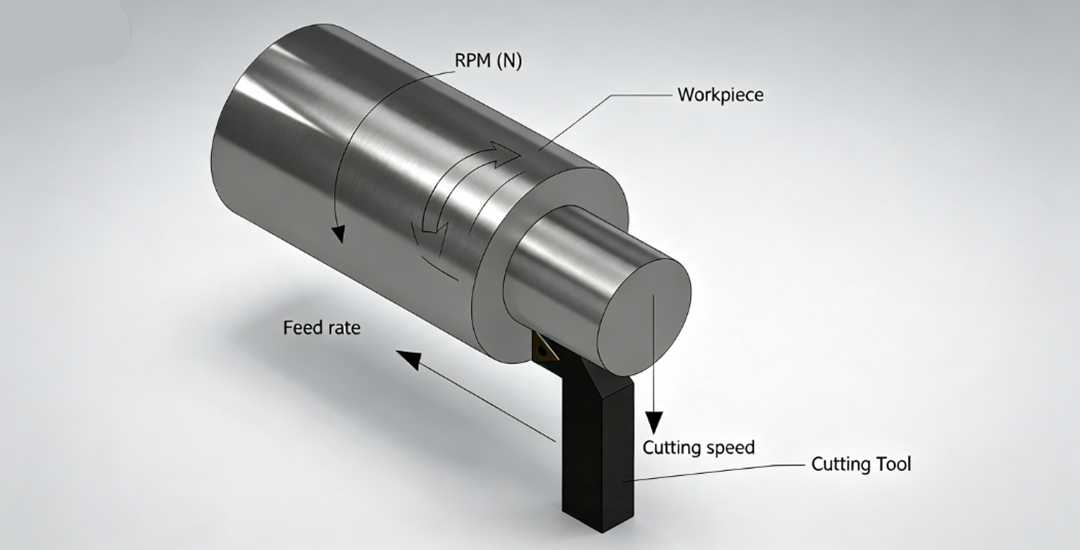
1. What is Cutting Speed?
Cutting speed is the relative linear speed between the cutting edge and the workpiece surface. It is commonly expressed in meters per minute (m/min) or surface feet per minute (SFM).
Cutting speed is related to spindle speed, but the two are not the same. Spindle speed describes how fast the spindle rotates in revolutions per minute (RPM), while cutting speed describes the surface velocity at the cutting point.
For metric calculations:
Cutting speed (Vc) = π × D × n / 1000
where:
- D = cutting diameter in millimeters
- n = spindle speed in RPM
The diameter used depends on the machining operation. In milling, it is based on the cutter diameter or effective cutting diameter. In turning, it is based on the workpiece diameter at the cutting point.
For example, a 10 mm end mill running at 8,000 RPM has a cutting speed of approximately 251 m/min. If the cutter diameter changes, the spindle speed must also change to maintain the same cutting speed.
Cutting speed strongly influences the temperature at the cutting edge and the rate of tool wear, which is why recommended values depend on the workpiece material, tool material, coating, and cutting conditions.
2. What Is Feed Rate?
Feed rate describes how quickly the cutting tool advances through the workpiece. Unlike cutting speed, its common expression depends on the machining operation.
Feed Rate in Turning
In turning, feed is commonly expressed as millimeters per revolution (mm/rev). This value represents how far the cutting tool moves along the workpiece during one spindle revolution.
The actual linear travel speed can also be expressed in millimeters per minute (mm/min):
Feed rate (mm/min) = feed per revolution × spindle speed
Feed Rate in Milling
In milling, feed is usually defined first as feed per tooth (fz), measured in millimeters per tooth. This describes how far the cutter advances as each cutting edge engages the material.
The machine then uses table feed:
Table feed (vf) = fz × n × z
where:
- fz = feed per tooth
- n = spindle speed in RPM
- z = number of effective cutting teeth
Feed has a strong influence on chip thickness, cutting forces, productivity, and surface finish. If feed is too low, the tool may rub instead of cutting efficiently. If it is too high, cutting forces and tool load can increase beyond what the tool or setup can support.
The correct feed therefore depends on the machining operation, tool geometry, workpiece material, engagement, and machine rigidity rather than on one universal value.
3. Cutting Speed vs Feed Rate: Key Differences
Cutting speed and feed rate describe different parts of the machining process. Cutting speed defines how fast the cutting edge moves relative to the workpiece surface, while feed defines how quickly the tool advances through the cut.
| Fator | Velocidade de corte | Feed Rate |
| What It Describes | Relative surface speed between the cutting edge and workpiece | Rate at which the tool advances through the cut |
| Common Units | m/min or SFM | mm/rev in turning; mm/tooth and mm/min in milling |
| Related Machine Setting | Spindle speed and cutting diameter | Feed per revolution, feed per tooth, and table feed |
| Primary Influence | Cutting temperature and tool life | Chip load, cutting force, surface finish, and productivity |
| If Set Too High | Excessive heat and faster tool wear | Higher cutting forces, heavy chip load, possible tool overload |
| If Set Too Low | Built-up edge or inefficient cutting may occur | Rubbing, poor chip formation, and longer cycle time |
The two parameters should not be adjusted independently. A workable combination also depends on tool geometry, workpiece material, depth of cut, engagement, coolant, and setup rigidity.
4. How Cutting Speed and Feed Work Together
Cutting speed and feed rate affect the same cutting process, so changing one can alter the conditions under which the other remains effective.
Cutting Temperature and Chip Load
Increasing cutting speed generally raises the temperature at the cutting edge and can accelerate tool wear. Increasing feed increases chip thickness and the amount of material removed by each cutting edge.
A stable process requires both values to stay within a range that the tool, material, and machine setup can support.
Cutting Forces
Feed has a strong influence on cutting forces because a heavier chip requires more force to remove. Cutting speed also affects forces indirectly through temperature, material behavior, and tool condition.
If the setup lacks rigidity, aggressive speed and feed combinations can increase vibration, deflection, or tool failure even when each value appears reasonable on its own.
Material Removal Rate
Productivity depends on more than spindle speed alone. Higher feed, greater depth of cut, and wider tool engagement can all increase material removal rate, while cutting speed determines how fast the cutting edge moves through the material.
For this reason, speed and feed should be optimized together with depth of cut, tool engagement, and machine capability rather than adjusted as independent settings.
5. How to Choose a Starting Speed and Feed
A reliable starting point should come from the cutting-tool manufacturer rather than from a universal speed-and-feed table. Recommended values are normally based on a specific tool, workpiece material group, and machining operation.
Start with the Workpiece Material and Tool
Material hardness, condition, and machinability influence the recommended cutting speed. Tool material, coating, diameter, insert geometry, and number of cutting edges also affect the usable range.
A carbide end mill for aluminum and a coated insert for stainless steel therefore require very different starting conditions, even if both operations are performed on the same machine.
Match the Parameters to the Operation
Turning, milling, drilling, roughing, and finishing place different loads on the cutting edge. Milling parameters also need to account for radial and axial engagement, because a tool making a light finishing pass does not experience the same chip load or heat as one taking a heavy roughing cut.
The manufacturer’s data should therefore be matched to the actual operation rather than applied only by material name.
Check Machine and Setup Rigidity
Tool overhang, workholding, spindle condition, part stiffness, and machine power can all reduce the practical speed and feed range.
Thin walls, long tools, or flexible setups may require more conservative parameters even when the tool manufacturer recommends higher values.
Once a stable starting point is established, adjust one parameter at a time while monitoring tool wear, chip formation, surface finish, and dimensional results. This makes it easier to identify which change actually improves the process.
6. Which Parameter Should You Adjust?
When a machining problem appears, cutting speed or feed may be part of the cause, but they should not be treated as the only variables. A useful approach is to identify which parameter to check first, then confirm the tool and setup conditions before making a large adjustment.
| Machining Problem | Check First | Also Check |
| Rapid tool wear | Cutting speed | Tool grade, coating, coolant, cutting stability |
| Rough surface finish | Feed and tool condition | Built-up edge, chatter, runout, cutting speed |
| Poor chip breaking | Feed / chip thickness | Tool geometry, depth of cut, coolant, cutting speed |
| Built-up edge | Cutting speed | Feed, edge sharpness, coolant, workpiece material |
| Excessive cutting force | Feed | Depth of cut, tool geometry, engagement, tool wear |
| Chatter or vibration | Setup rigidity and spindle speed | Tool overhang, depth of cut, feed, workholding |
| Long cycle time | Feed and material removal strategy | Cutting speed, depth of cut, engagement |
The table is a starting point rather than a fixed troubleshooting rule. For example, reducing cutting speed may help rapid flank wear, but the real cause could also be an unsuitable tool grade or poor coolant delivery.
Likewise, reducing feed can improve surface finish in some cases, but it will not solve chatter, runout, built-up edge, or a worn cutting edge. The best adjustment depends on the complete cutting condition.
7. How Speed and Feed Affect Tool Life, Surface Finish, and Productivity
Cutting speed and feed rate influence machining results in different ways, but their effects often overlap. The goal is to find a combination that delivers the required part quality without sacrificing tool life or cycle efficiency.
Tool Life
Cutting speed usually has a strong influence on tool life because higher surface speed increases temperature and wear at the cutting edge.
Feed also affects tool load and wear, particularly when chip thickness or cutting forces become too high. Tool life therefore depends on the complete cutting condition rather than cutting speed alone.
Acabamento de superfície
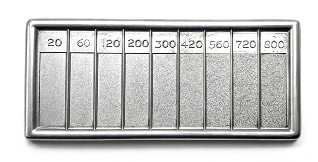
Feed has a direct influence on the tool marks left on the machined surface. Lower feed can improve theoretical surface quality, especially during finishing, but reducing it too far may cause rubbing instead of effective cutting.
Actual surface finish also depends on tool geometry, tool wear, runout, built-up edge, vibration, and cutting speed. A poor finish should therefore not automatically be treated as a feed-rate problem.
Productivity
Feed rate, depth of cut, and tool engagement have a major influence on material removal rate and cycle time. Increasing cutting speed may also improve productivity, but it can increase heat and shorten tool life.
For a stable process, productivity improvements should be evaluated against tool wear, surface requirements, machine power, and setup rigidity rather than by increasing speed or feed alone.
Conclusão
Cutting speed and feed rate should be treated as a matched set rather than two independent machine settings. The right combination depends on the material, tool, operation, engagement, and setup stability.
For CNC machining projects, Beska can support process review, parameter optimization, machining, and dimensional inspection from prototype through production.
 Portuguese
 English
 Hebrew
 Turkish
 French
 Russian
 German
 Spanish