


During bending, sheet metal stretches on the outside and compresses on the inside, changing the length of the flat pattern. If this material deformation is not considered during design, the finished part may not meet its intended dimensions, resulting in assembly issues, rework, or scrap.
Bend allowance accounts for this change by calculating the additional material required in the bend region. It is a fundamental part of sheet metal design and directly affects flat pattern accuracy, manufacturing cost, and final part quality.
This guide explains how bend allowance is calculated, how the K-factor and bending method influence the result, and the practical design considerations for producing accurate bent parts.
1. What Is Bend Allowance?
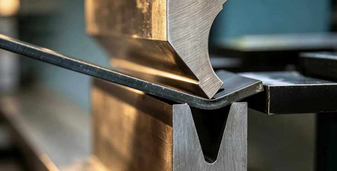
When sheet metal is bent, the outside surface stretches while the inside surface compresses. Between them lies the neutral axis, where the material neither stretches nor compresses. Bend allowance is the length of the bend measured along this neutral axis and is used to calculate the correct flat pattern.
In practice, bend allowance represents the additional material required in the bend region so the finished part reaches the intended dimensions after forming. Without it, the flat pattern will be either too short or too long.
The total flat length is calculated as: Lt = A + B + BA
Where:
- Lt = total flat length
- A and B = flange dimensions (measured to the bend tangent points)
- BA = bend allowance
Every flat pattern calculation depends on bend allowance. Whether the part is developed in CAD or calculated manually, using the correct bend allowance is essential for achieving accurate formed dimensions.
2. Bend Allowance vs Bend Deduction
Bend allowance (BA) and bend deduction (BD) are closely related, but they are used from different dimensional references. Choosing the correct method depends on how the part dimensions are defined on the drawing.
Bend allowance (BA) is added to the sum of the inside flange dimensions to calculate the flat pattern, while bend deduction (BD) is subtracted from the sum of the outside dimensions. Although the calculation methods differ, both are intended to produce the same flat blank when applied correctly.
The relationship between them is: BD = (OSSB × 2) – BA
Where OSSB (Outside Setback) is the distance from the bend tangent point to the bend apex. Once the OSSB is known, bend allowance and bend deduction can be converted directly from one another.
| Recurso | Bend Allowance (BA) | Bend Deduction (BD) |
| Calculation Method | Added to the sum of inside flange dimensions. | Subtracted from the sum of outside flange dimensions. |
| Reference Dimension | Works with Inside dimensions. | Works with Outside dimensions. |
| Typical Application | Preferred in CAD/CAM software for flat pattern generation. | More common for manual shop-floor calculations. |
| Common Use | When the design is based on internal features or cavity sizes. | When the drawing specifies overall external part size. |
CAD software typically uses bend allowance, while bend deduction is often used for calculations based on outside dimensions. The important thing is to choose one method and use it consistently throughout the design.
3. The K-Factor: Why It Matters
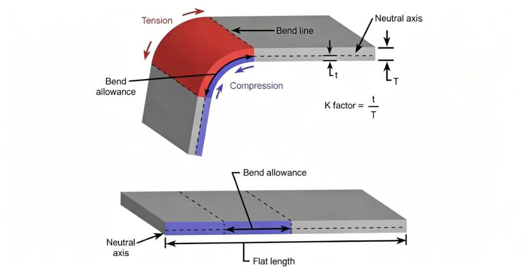
The accuracy of bend allowance depends largely on the K-factor. It describes the position of the neutral axis relative to the material thickness and determines how much material is included in the bend calculation.
Before bending, the neutral axis lies near the middle of the sheet. As the material is formed, it shifts toward the inside surface. A K-factor of 0.5 indicates no shift, while lower values indicate the neutral axis moves closer to the inside bend radius.
For mild cold-rolled steel, a K-factor of approximately 0.446 is commonly used as an initial design value. However, the actual value depends on the material, thickness, bending method, tooling, and inside bend radius. Air bending typically produces K-factors between 0.3 and 0.5, while bottoming usually results in values around 0.33.
The standard bend allowance equation is: BA = π × (R + K × T) × (θ / 180)
Where:
- R = inside bend radius
- K = K-factor
- T = material thickness
- θ = bend angle (degrees)
For quick estimates of 90° steel bends, the following simplified equation is commonly used:
BA = (0.017453 × R + 0.0078 × T) × Bend angle
Published K-factor values provide a useful starting point, but they should always be verified for the actual production process. A simple test bend using the intended material, tooling, and press brake produces more reliable results than relying solely on generic reference charts or handbook values.
4. How Bending Method Affects Bend Allowance
The bending method directly affects the K-factor and therefore the bend allowance used to calculate the flat pattern.
Air bending is the most common sheet metal bending process. Because the punch does not fully press the material into the die, the inside bend radius depends on the die opening rather than the punch radius. As a result, the K-factor typically varies between 0.3 and 0.5, making bend allowance less predictable.
Bottoming forces the material deeper into the die, producing a more consistent inside bend radius. Since the bend geometry is controlled more precisely, the K-factor is generally more stable, typically around 0.33.
Coining applies enough force to plastically deform the material at the bend. This greatly reduces springback and produces the most consistent bend geometry, but it requires significantly higher forming force, increases tool wear, and is generally reserved for high-precision applications.
| Recurso | Dobra de ar | Fundo | Cunhagem |
| Fator K | Varies (0.3–0.5) | More predictable (~0.33) | Lower, more consistent |
| Precision/Accuracy | Moderado | Alto | Muito alto |
| Cost / Tonnage | Baixo | Médio | High (5-8x more force) |
| Retorno elástico | High, requires compensation | Moderado | Mínimo |
| Typical Application | General fabrication, prototypes | Precision parts, consistent geometry | High-precision, critical dimensions |
If the bend allowance is calculated for one bending method but manufactured using another, the flat pattern may no longer produce the intended dimensions. The bending method should therefore be confirmed before the flat pattern is finalized.
5. How Material Affects Bend Allowance
Different materials respond differently during bending, which changes the position of the neutral axis and affects both the K-factor and bend allowance. Material properties such as strength, ductility, and springback all influence the final flat pattern.
- Mild steel is the easiest material to bend and provides predictable results in most applications. A K-factor of approximately 0.446 is commonly used as a starting point, and standard bend tables are suitable for many general fabrication jobs.
- Stainless steel produces greater springback and requires more forming force because of its higher strength. A K-factor of approximately 0.42–0.43 is often used, although the actual value depends on the material grade and bending process.
- Aluminum requires less bending force than steel, but its behavior varies more between alloys. Higher-strength grades are more prone to cracking with tight bend radii, and additional angle compensation is often needed to account for springback.
- Material thickness also affects bend allowance. As sheet thickness increases, small variations in the K-factor have a greater effect on flat pattern dimensions, making process validation more important for precision parts.
Published K-factor values should be treated as starting points. For critical applications, trial bends and production bend tables provide the most reliable bend allowance values.
6. How to Specify Bend Allowance During Design
Specifying bend allowance correctly requires more than selecting a formula. The bending method, tooling, material, and design intent should all be considered before the flat pattern is finalized.
- Determine the inside bend radius. Avoid selecting an arbitrary radius. For air bending, a practical starting point is often to set the inside radius equal to the material thickness (R = T), although the actual radius is influenced by the die opening. For bottoming and coining, the inside radius is typically controlled by the punch nose radius.
- Select an appropriate K-factor. Standard K-factor values are suitable for prototypes and general fabrication, but production parts should use validated bend tables or K-factors established through trial bends using the actual material, tooling, and bending process. Published values should be treated as reference data rather than fixed design values.
- Define the critical dimensions. Clearly identify the dimensions that affect fit and function, and avoid unnecessary tight tolerances. This gives the manufacturer greater flexibility to achieve the required geometry without increasing manufacturing complexity.
- Verify the flat pattern in CAD. Use the sheet metal module to generate the flat pattern based on the selected bend radius, material thickness, and K-factor. Reviewing the formed model before release helps identify potential issues early in the design process.
- Confirm the bending process with your manufacturer. Differences in tooling, bending method, or production setup can affect the final bend allowance. A Design for Manufacturability (DFM) review helps ensure that the selected parameters are suitable for the intended manufacturing process.
Accurate bend allowance depends on both sound design decisions and a manufacturing process capable of producing them consistently.
7. Common Mistakes in Bend Allowance Calculation
Many bend allowance problems can be traced back to a few common mistakes during design and calculation.
- Treating the K-factor as a constant. Using the same K-factor for every material and thickness often leads to inaccurate flat patterns because the neutral axis shifts under different bending conditions.
- Confusing the inside radius with the punch radius. In air bending, the inside radius is determined primarily by the die opening rather than the punch tip radius. Specifying an unrealistically small inside radius may exceed the material’s forming capability and increase the risk of cracking.
- Ignoring springback. Different materials recover differently after bending. Without proper angle compensation, the finished bend angle may not match the design.
- Placing features too close to bend lines. Holes, slots, and tabs should generally be located at least four times the material thickness from the bend line to minimize distortion during forming.
- Overlooking tolerance stack-up. Small variations from each bend can accumulate across multiple bends, making dimensional errors more noticeable on complex parts.
Many flat pattern problems are caused by bending parameters that do not match the actual manufacturing process. Verifying the bend radius, K-factor, and bending method before production helps reduce rework and improve dimensional accuracy.
8. Real-World Applications
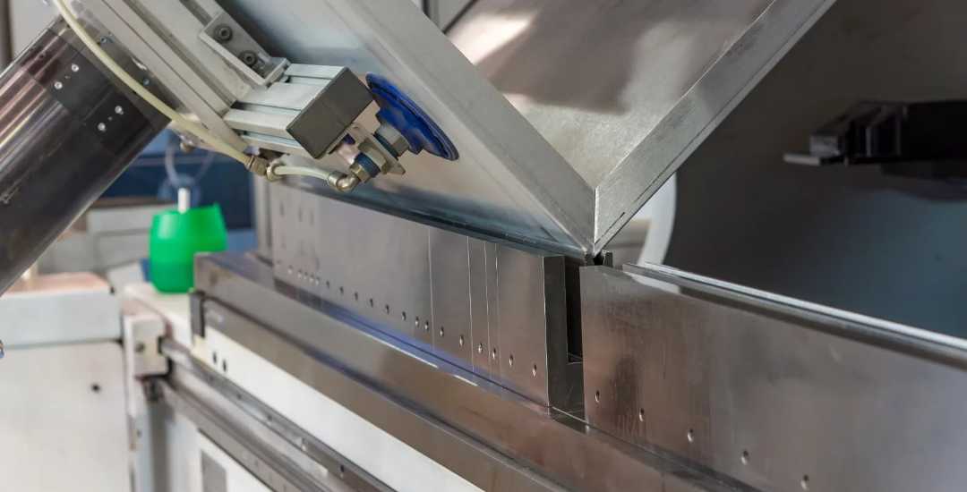
Accurate bend allowance is essential across a wide range of sheet metal products, although the manufacturing challenges vary with the application.
Electronic Enclosures
Electronic enclosures often contain four or more bends that form a closed assembly. Small dimensional errors accumulate with each bend, affecting panel fit and hole alignment. Many manufacturers use bottoming or validated bend tables to improve dimensional consistency for these parts.
Automotive Brackets
Automotive brackets typically include two or three bends and must fit within limited installation space. High-strength steels produce greater springback than mild steel, making bend compensation more important. Dimensions referenced across multiple bends are also more susceptible to tolerance stack-up.
Industrial Equipment Frames
Machine frames are commonly manufactured from thicker sheet metal or plate, where structural strength is the primary requirement. Material thickness variation, residual stress, and welding distortion all influence the final geometry, making validated bend allowance especially important for large fabricated structures.
Accurate bend allowance helps ensure that formed parts meet their intended dimensions, regardless of whether the product is an electronics enclosure, an automotive bracket, or an industrial frame.
Conclusão
Bend allowance is a fundamental part of sheet metal design. Accurate flat patterns depend on selecting the appropriate bend radius, K-factor, material, and bending process rather than relying on standard values alone. Small differences in these variables can lead to dimensional errors after forming.
Successful sheet metal bending starts with validated data and a manufacturing process that matches the design intent. Verifying bending parameters before production helps improve dimensional consistency and reduces unnecessary adjustments during manufacturing.
At Beska, we apply these principles to every sheet metal project through DFM reviews, validated bend tables, and production-tested processes. If you need support with a bent sheet metal design, our engineering team can review your drawings and help identify potential manufacturing issues before production begins.
Deeper into Our Resources
For some insightful reads, we’ve curated a list of recommended articles just for you:
 Portuguese
 English
 Hebrew
 Turkish
 French
 Russian
 German
 Spanish