


A shaft comes off the lathe with two coaxial diameters. The drawing specifies concentricity, but the inspector checks the part with a dial indicator and records a Total Indicator Reading (TIR). The supplier ships the part, only for the customer to reject it. The problem is not the machining process. The drawing specified one GD&T control, while the inspection verified another. Runout and concentricity are different controls, and they are not interchangeable.
This confusion affects how parts are specified, inspected, and accepted. Selecting the wrong callout can lead to unnecessary CMM inspections when a dial indicator would be sufficient, or worse, allow parts that satisfy a geometric tolerance but still perform poorly in service.
This article explains what runout and concentricity control under ASME Y14.5, how each is inspected, why concentricity was removed from the 2018 standard, and how to choose the right GD&T callout for rotating parts.
1. Runout and Concentricity: What Each One Measures
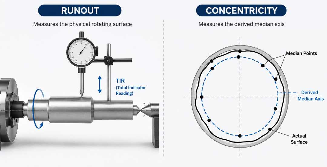
Before comparing the two, it helps to define each control in practical shop-floor terms.
Runout measures how much a surface deviates as a part rotates about a datum axis. The inspector places a dial indicator on the surface, rotates the part through one full revolution, and records the Total Indicator Reading (TIR). That single reading reflects both the condition of the rotating surface and its relationship to the datum axis. Runout is divided into circular runout, which is measured at a single cross-section, and total runout, which is measured along the entire surface.
Concentricity evaluates whether the median points of a feature, determined from diametrically opposed measurements at multiple cross-sections, remain within a cylindrical tolerance zone centered on the datum axis. Unlike runout, concentricity evaluates the theoretical median axis rather than the physical surface. A part with significant lobing or other surface form errors may still satisfy a concentricity requirement if the median axis remains within tolerance.
Although both controls relate to coaxial features, they evaluate different characteristics. Runout reflects the combined effects of surface form and feature location, while concentricity evaluates only the theoretical median axis. A part with perfect runout will also satisfy concentricity, but a part that satisfies concentricity may still fail runout because the rotating surface is out of round. For rotating components such as shafts, bearing journals, and seal surfaces, runout is therefore the more functionally meaningful control.
2. Advantages of Runout as a Callout
Because runout evaluates both surface form and feature location in a single measurement, it is the preferred GD&T control for most rotating parts. Compared with concentricity, runout offers two practical advantages on the shop floor.
1. Faster and more practical inspection
Runout is measured with a dial indicator and a V-block or centers. Setup is quick, and the reading is available immediately. A shop can inspect an entire production lot in the time required to complete a single CMM concentricity routine. More importantly, the TIR reading directly reflects functional performance. A bearing journal with acceptable runout rotates smoothly, while a seal surface held to a tight TIR helps maintain sealing performance.
2. Better measurement repeatability
Runout inspection is highly repeatable across operators and equipment. Concentricity results, however, can vary depending on the number of measurement sections, sampling strategy, and CMM software algorithm. When suppliers and customers obtain different results, the difference usually comes from the inspection method rather than the quality of the part itself.
For rotating components, runout is not only easier to inspect but also more closely related to actual service performance. This is one of the main reasons why modern GD&T practice favors runout and position for new designs, while ASME Y14.5-2018 removed concentricity from the standard.
3. Why Concentricity Causes Problems on the Shop Floor
Concentricity appears precise on engineering drawings, but it creates two major challenges during inspection and production.
1. The measurement is complex and time-consuming
Concentricity requires extracting median points from multiple cross-sections, constructing a derived median axis, and verifying that it remains within the specified tolerance zone. This process typically requires a CMM and is considerably more time-consuming than measuring runout with a dial indicator. Results may also vary depending on probe strategy, sampling method, and CMM software algorithm, making repeatable measurement more difficult.
2. It does not control the functional surface
Concentricity evaluates the theoretical median axis rather than the physical surface. A part with significant lobing can still satisfy a concentricity requirement if the median axis remains within tolerance, yet the same part may fail runout and vibrate during operation. In other words, concentricity controls a theoretical geometric condition while leaving the rotating surface that determines real-world performance uncontrolled.
ASME Y14.5-2018: Concentricity Removed from the Standard
These limitations eventually led to a change in the GD&T standard itself. ASME Y14.5-2018 removed concentricity, recognizing that runout and position provide clearer, more repeatable, and function-oriented geometric controls.
ASME Y14.5-2009 was the last edition to include concentricity, so the symbol still appears on many legacy drawings. For new designs, however, runout or position should be used instead. When reviewing older drawings, consider updating the callout during the next design revision rather than carrying it forward unchanged.
Together, these technical limitations explain why concentricity has largely disappeared from modern GD&T practice. Unless you are working with a legacy drawing or a rare application that specifically requires median-axis control, there is little reason to specify concentricity today.
4. Where These Callouts Matter: Real Parts
The difference between runout and concentricity becomes much clearer when applied to real production parts. The following examples show how the choice of GD&T callout affects manufacturing, inspection, and functional performance in components commonly produced at Beska.
Bearing Journals on Transmission Shafts

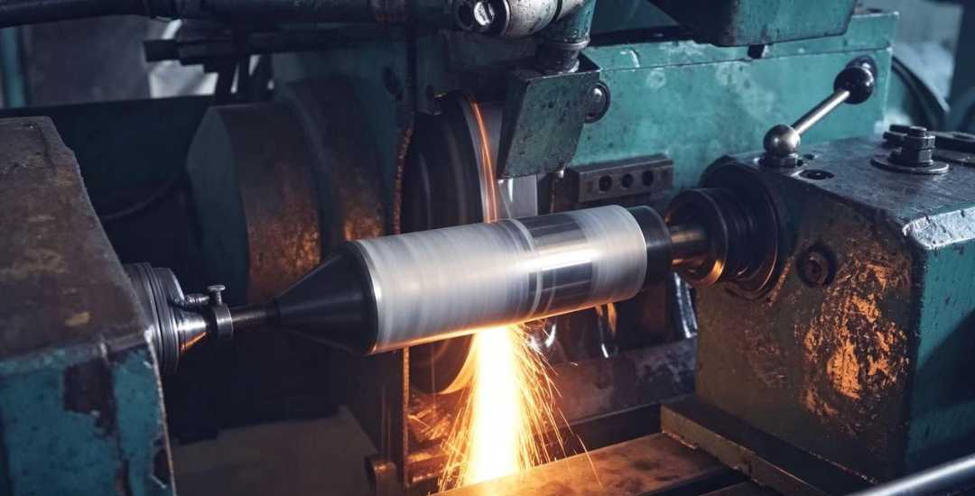
Runout is the correct callout because the bearing depends on a true rotating surface. Concentricity would not detect an out-of-round journal if its median axis remained within tolerance. Holding tight runout across multiple bearing journals typically requires grinding between centers after heat treatment.
Manufacturing focus: Grind all bearing journals in a single setup between centers so they share the same datum axis.
Seal Surfaces on Pump Shafts
A lip seal contacts the shaft surface directly. If the shaft has excessive runout, the seal experiences a changing gap during every revolution, increasing the risk of leakage. Runout therefore predicts sealing performance much better than concentricity, since a perfectly centered but lobed surface can still leak.
Manufacturing focus: Finish the seal surface in the same setup as the bearing journal to maintain datum consistency.
Medical Tubing and Cannula
Concentricity still appears on some medical drawings for thin-wall tubing where wall thickness uniformity is important. In practice, many manufacturers verify wall thickness directly with optical measurement systems instead of calculating concentricity from median points.
Manufacturing focus: Use controlled drawing processes or centerless grinding to achieve consistent wall thickness during manufacturing.
These examples illustrate a simple engineering principle: select the GD&T control according to the functional requirement of the part, not simply the geometric feature. For rotating surfaces, runout is generally the preferred control. When wall thickness uniformity is the real requirement, direct wall thickness measurement is usually more meaningful than specifying concentricity.
5. Runout vs Concentricity: Direct Comparison
Although runout and concentricity both apply to coaxial features, they control different aspects of part geometry and serve different engineering purposes. Runout evaluates the physical rotating surface, while concentricity evaluates the theoretical median axis. The comparison below summarizes their key differences in function, inspection, applications, and current GD&T practice.
| Особенность | Runout | Concentricity |
| Основная цель | Controls the physical rotating surface | Controls the theoretical median axis |
| What It Evaluates | Surface form and location during rotation | Median points relative to the datum axis |
| Typical Inspection Method | Dial indicator on centers or V-blocks | CMM using median-point calculation |
| Inspection Speed | Fast and suitable for production inspection | Slow and more complex |
| Measurement Repeatability | Высокий | Depends on sampling strategy and CMM algorithm |
| Functional Performance | Directly reflects bearing, seal, and rotating component performance | Does not necessarily predict service performance |
| Surface Form Considered | Да | Нет |
| Распространенные приложения | Bearing journals, shafts, seal diameters, rotating hubs | Legacy drawings, specialized tubing applications |
| Recommended for New Designs | Да | Rarely |
| ASME Y14.5-2018 Status | Fully supported | Removed from the standard |
For most engineering applications, runout is the preferred choice because it directly evaluates the surface that affects functional performance and can be verified quickly and consistently on the shop floor. Concentricity should generally be reserved for legacy drawings or the rare situations where controlling the derived median axis is the actual design requirement.
Sources: ASME Y14.5-2018; ISO 1101:2017; Machinery’s Handbook, 31st ed., Industrial Press, 2020; ASME Y14.5.1-2019
6. How to Choose the Right GD&T Callout
The comparison table above explains what each control measures, but selecting the correct GD&T callout depends on how the part functions, how it will be inspected, and which drawing standard applies. In most cases, the decision can be made by answering four practical questions.
What is the functional requirement?
Start by identifying what the feature does in service. If the surface contacts a bearing, seal, or mating hub during rotation, runout is the appropriate control because it evaluates the rotating surface directly. When wall thickness uniformity is the true requirement, direct wall thickness measurement or position tolerance is generally more appropriate. Concentricity is only justified when the derived median axis itself is the functional requirement, which is uncommon in modern designs.
How will the part be inspected?
The GD&T callout should match the available inspection method. Runout is easily verified with a dial indicator on centers or V-blocks. Position is typically measured on a CMM using a simpler and more repeatable evaluation than concentricity. Because concentricity requires median-point calculation across multiple sections, its results are more sensitive to measurement strategy. Avoid specifying a tolerance that cannot be verified reliably with the intended inspection method.
Does the part rotate in service?
For rotating components, runout is generally the preferred control because the TIR reading directly reflects how the surface behaves during operation. For non-rotating coaxial features, such as locating pilot bores, position tolerance is usually the better choice. Concentricity is not recommended for new rotating designs because it is no longer included in ASME Y14.5-2018.
Which drawing standard applies?
If the drawing follows ASME Y14.5-2018, concentricity is not available and should not be specified. Use runout or position instead. If an older edition such as ASME Y14.5-2009 is referenced, concentricity is technically permitted but is generally discouraged for new designs. For legacy drawings already in production, retain the existing callout until the next approved design revision.
In most engineering applications, the selection is straightforward: use runout for rotating surfaces, use position for non-rotating coaxial features, and reserve concentricity for legacy drawings or the rare cases where controlling the median axis is the actual functional requirement.
7. Holding Runout in Production: Setup, Datum, and Process
Specifying a tight runout tolerance on a drawing is only the first step. Whether a part actually meets that requirement depends on machining strategy, datum control, inspection practice, and process stability throughout production.
Стратегия обработки
The most effective way to achieve tight runout is one-setup machining. When all coaxial features are turned or ground in a single chucking, they naturally share the same spindle axis, minimizing accumulated alignment error. Every re-chucking introduces the possibility of datum shift caused by jaw alignment or clamping force, making it one of the most common causes of excessive runout.
For long shafts, обработка или шлифовка between centers is often the preferred approach. When a part must be re-chucked, a precision soft jaw bored to the finished locating diameter helps preserve the original datum relationship. At Beska, fixture strategy is reviewed during the quoting stage whenever tight runout requirements are specified.
Common mistake: A part may satisfy concentricity on a CMM but still fail runout inspection because the rotating surface itself is not controlled.
Cutting Conditions
Surface condition also influences runout measurement. A dial indicator follows the actual surface, so excessive roughness, chatter marks, or tool wear can increase the Total Indicator Reading (TIR) even when the underlying geometry is acceptable.
For critical rotating surfaces, use a finishing process capable of producing a stable surface finish. Replace worn inserts before cutting forces become unbalanced, and use a follow rest or similar support when machining long, slender shafts to minimize deflection.
Common mistake: Before rejecting a part for excessive runout, confirm whether the reading is caused by true geometric error or by surface finish irregularities.
Inspection and Datum Selection
The datum axis used for runout inspection should always represent the functional rotation axis. For a shaft supported by bearing journals, those journals should define the inspection datum. A common mistake is using a center-drill hole as the only datum. If the center hole is slightly offset, the indicator measures error relative to the hole instead of the axis that actually supports the bearing.
Runout is typically inspected using a dial indicator on centers or V-blocks. At Beska, dial-indicator inspection is the default method for runout verification, while any concentricity requirement is reviewed by engineering before production begins.
Стабильность процесса
Process stability has a direct impact on runout performance. Residual stress remaining after rough machining may cause a shaft to distort over time, allowing a part that initially passed inspection to fail later. Rough machining, stress relief where appropriate, and finish machining after stabilization help minimize this effect.
Heat treatment can also introduce distortion by changing the geometry of previously machined features. For hardened shafts, finish grinding and final runout inspection should be performed after heat treatment, since the post-heat-treat condition represents the functional geometry of the finished part.
Key Takeaway
Achieving tight runout depends on process control rather than tolerance specification alone. One-setup machining, proper datum selection, stable machining conditions, and inspection after critical manufacturing processes are the key factors that determine whether a part consistently meets its runout requirement. In practice, a well-planned manufacturing process contributes just as much to successful runout control as the GD&T callout shown on the drawing.
8. When to Use Runout vs Concentricity
Selecting the correct GD&T control depends on how the part functions in service, how it will be inspected, and which drawing standard applies. The table below summarizes the recommended callout for the most common engineering situations.
In most applications, runout is the preferred control for rotating surfaces because it directly evaluates the condition that affects functional performance. When wall thickness uniformity is the true design requirement, direct wall thickness measurement or position tolerance is generally more appropriate. Concentricity should be reserved for legacy drawings or the rare applications where controlling the derived median axis is the actual functional requirement.
The guiding principle is simple: select the GD&T callout according to part function and inspection method rather than following historical drawing practices. Legacy callouts should be reviewed during design updates instead of being carried forward without evaluating whether they still represent the functional requirement.
Заключение
The right GD&T callout is the one that reflects how a part functions in service. For rotating components, runout directly evaluates the surface that bearings, seals, and mating parts actually contact, making it the preferred control for most applications. Concentricity should generally be reserved for legacy drawings or the rare cases where the median axis itself is the functional requirement.
Before releasing a drawing, verify three things: the functional requirement, the inspection method, and the applicable drawing standard. Choosing the correct GD&T control at the design stage helps avoid inspection disputes, unnecessary manufacturing costs, and production delays.
At Beska, we review datum selection, GD&T callouts, and inspection methods before machining begins, helping customers ensure that the specified tolerance matches both the manufacturing process and the functional requirements of the finished part.
 Russian
 English
 Hebrew
 Turkish
 French
 German
 Spanish
 Portuguese