


A weld can look sound on the surface and still contain porosity, lack of fusion, incomplete penetration, or cracking. Some defects are visible during inspection, while others remain inside the joint and require nondestructive testing.
Their causes differ. Contamination and poor shielding can create porosity, incorrect heat input or joint preparation can prevent proper fusion, and cracking may be related to hydrogen, material properties, or joint restraint.
This article covers the main types of welding defects, how they form, their effects on the joint, and the inspection and prevention methods used in manufacturing.
1. What Is a Welding Defect?
A welding discontinuity is an irregularity in the weld or surrounding material, such as porosity, undercut, slag inclusion, or lack of fusion. The presence of a discontinuity does not automatically mean that the weld must be rejected.
A discontinuity becomes a defect when it exceeds the applicable acceptance criteria. These limits may come from the engineering drawing, contract requirements, or the welding code or specification used for the project.
This distinction matters because some small imperfections may be acceptable, while cracks or other critical discontinuities may require repair or rejection depending on the applicable standard. Inspection should therefore judge the weld against defined acceptance criteria rather than appearance alone.
2. Common Types of Welding Defects
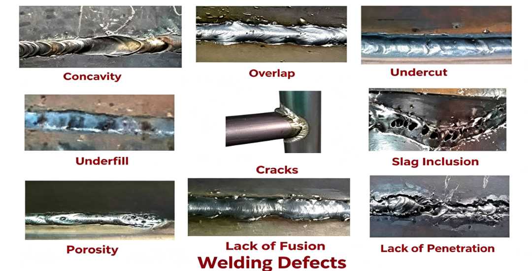
Welding discontinuities can appear on the weld surface, at the joint root, or completely inside the weld. Their effect depends on the type, size, location, and acceptance criteria specified for the part.
Пористость
Porosity appears as rounded cavities or small gas pockets in the weld metal. It is commonly associated with moisture, surface contamination, inadequate shielding gas, or contaminants entering the weld pool.
Excessive porosity can reduce the effective weld section and may create leak paths or reduce fatigue performance. Clean joint surfaces, dry consumables, and stable shielding gas coverage are important for prevention.
Welding Cracks
Cracks are sharp fracture-type discontinuities that may form in the weld metal or heat-affected zone. Hot cracks develop at elevated temperatures during or shortly after solidification, while cold cracks can form later and, in steels, are often associated with hydrogen, a susceptible microstructure, and high restraint.
Because their sharp tips can propagate under stress, cracks are among the most serious welding discontinuities and are generally not permitted by fabrication codes. Prevention depends on the crack mechanism and may involve material selection, hydrogen control, heat input, joint design, and welding procedure control.
Lack of Fusion
Lack of fusion occurs when weld metal does not properly fuse with the base metal or a previous weld pass. Common causes include insufficient heat input, excessive travel speed, incorrect electrode or torch angle, and poor access to the joint sidewall.
The unfused interface reduces the effective load-carrying area and can act as a stress concentrator. Proper joint preparation, suitable welding parameters, and correct torch positioning help reduce the risk.
Incomplete Penetration
Incomplete penetration occurs when the weld does not extend through the required joint root. It can result from unsuitable joint preparation, insufficient root opening, inadequate heat input, or poor access to the root.
The result may be a smaller effective weld section than the design requires. Correct fit-up, joint preparation, and welding parameters are therefore important before the root pass is made.
Undercut
Undercut is a groove melted into the base metal along the weld toe or root that is not completely filled with weld metal. Excessive welding current, high travel speed, incorrect arc length, or poor electrode positioning can contribute to its formation.
Because undercut reduces the local section and creates a notch at the weld edge, it can increase stress concentration and affect fatigue performance. Controlling welding parameters and maintaining proper torch or electrode technique can reduce it.
Slag Inclusion
Slag inclusions are nonmetallic material trapped within the weld or between weld passes. They are most closely associated with flux-based processes and can form when slag is not completely removed between passes or when weld bead shape traps slag in the joint.
Good interpass cleaning, suitable joint preparation, and welding technique that allows slag to escape help prevent inclusions.
Overlap
Overlap occurs when weld metal flows onto the base material without properly fusing to it. It is often associated with poor electrode or torch manipulation, an excessively large weld pool, or contamination and oxide on the base material.
The unfused edge creates an unfavorable weld profile and may act as a stress concentration point. Controlling weld pool size, travel technique, and surface preparation helps prevent it.
Cracks, lack of fusion, and incomplete penetration are generally more critical than rounded volumetric discontinuities such as porosity because their geometry can create sharper stress concentrations. However, whether any discontinuity requires repair should still be determined by the applicable drawing, specification, or welding code.
3. Welding Defects by Welding Process
Different welding processes have different defect tendencies because they use different electrodes, shielding methods, filler metals, and heat input.
| Welding Process | Common Defect Tendencies | Typical Causes | Prevention Focus |
| MIG (GMAW) | Porosity, spatter, lack of fusion | Poor shielding, contaminated wire or base metal, incorrect parameters | Stable gas coverage, clean wire and joint surfaces, correct voltage and wire feed settings |
| TIG (GTAW) | Tungsten inclusion, porosity, lack of fusion | Tungsten contacting the weld pool, poor shielding, insufficient heat input | Keep the electrode out of the weld pool, maintain gas coverage, control heat input |
| Stick (SMAW) | Slag inclusion, porosity, hydrogen-related cracking | Poor slag removal, damp electrodes, incorrect technique | Proper electrode storage, interpass cleaning, suitable welding technique |
| FCAW | Slag inclusion, porosity, lack of fusion | Poor interpass cleaning, shielding problems, incorrect parameters | Clean between passes, maintain shielding, follow suitable welding parameters |
The process often points to where troubleshooting should begin. Porosity in MIG welding usually directs attention to shielding gas and contamination, slag inclusion in SMAW or FCAW often leads back to interpass cleaning and bead placement, while tungsten inclusion is closely tied to TIG electrode handling.
4. How to Prevent Welding Defects
Most welding defects can be reduced by controlling the joint condition, consumables, shielding, and welding parameters before problems appear in the finished weld.
Joint Preparation and Cleanliness
Poor fit-up can lead to incomplete penetration, lack of fusion, and inconsistent weld geometry. Root opening, bevel angle, alignment, and joint access should match the welding procedure before welding begins.
Oil, rust, paint, oxide, moisture, and other contaminants should also be removed from the weld area. These materials can interfere with fusion or release gas into the weld pool, increasing the risk of porosity and inclusions.
Consumables and Shielding
Electrodes, filler wire, and flux-cored consumables should be stored and handled according to their specified conditions. Moisture pickup or surface contamination can introduce hydrogen or other gases into the weld.
For gas-shielded processes, stable gas coverage is equally important. Leaking hoses, blocked nozzles, excessive drafts, or incorrect gas flow can expose the weld pool to the atmosphere and increase porosity or oxidation.
Welding Parameters and Heat Control
Voltage, current, wire feed speed, travel speed, and torch or electrode position should stay within the qualified welding procedure. Too little heat can cause lack of fusion or incomplete penetration, while excessive heat can increase distortion, undercut, or cracking risk.
Preheat and interpass temperature should be controlled when required by the material, joint thickness, hydrogen level, or welding procedure. These values should come from the applicable WPS or engineering specification rather than a fixed rule applied to every weld.
5. How Welding Defects Are Inspected
The inspection method depends on whether the suspected defect is open to the surface or hidden inside the weld.
| Inspection Method | Best Suited For | Main Limitation |
| Visual Testing (VT) | Undercut, overlap, surface cracks, visible porosity, weld profile problems | Cannot detect hidden internal defects |
| Liquid Penetrant Testing (PT) | Fine surface-breaking cracks and porosity on nonporous materials | Only detects defects open to the surface |
| Magnetic Particle Testing (MT) | Surface and near-surface cracks in ferromagnetic steels | Cannot be used on aluminum or austenitic stainless steel |
| Ultrasonic Testing (UT) | Internal cracks, lack of fusion, and other planar discontinuities | Detection depends on defect orientation, geometry, and operator technique |
| Radiographic Testing (RT) | Internal porosity, slag inclusions, incomplete penetration, and other volumetric defects | Tight planar defects can be difficult to detect when poorly oriented to the radiation beam |
Visual inspection is normally the first step because many surface defects and weld-profile problems can be identified before more advanced testing is used. PT or MT can then be used when surface cracking is a concern, while UT and RT are more suitable when internal weld quality needs to be evaluated.
UT is often effective for planar discontinuities such as lack of fusion, while RT provides a clearer image of many volumetric defects such as porosity. The final method should match the expected defect, material, joint geometry, and inspection requirements specified for the weld.
Заключение
Welding defects should be evaluated against the drawing, specification, or applicable welding code rather than appearance alone. Finding a discontinuity is only the first step; preventing it from returning requires identifying whether the problem came from joint preparation, contamination, shielding, welding parameters, material behavior, or heat control.
For welded sheet metal parts, Beska manufactures according to drawing and specified welding requirements, with joining, finishing, and assembly considered as part of the overall production process.
 Russian
 English
 Hebrew
 Turkish
 French
 German
 Spanish
 Portuguese