


In manufacturing, machining, and mechanical maintenance, thread measurement is not only a technical step but also a core element of quality assurance. Whether it is a bolt in an automotive engine, a sealing pipe connection in a fluid system, or a micro-thread inside a precision device, accurate measurement directly affects assembly performance, safety, and service life. Research indicates that close to 30% of thread-related failures originate from incorrect sizing or improper inspection, which underscores the importance of knowing how to measure threads correctly.
This article explains thread fundamentals, common measuring tools, practical measurement methods for external and internal threads, tolerance evaluation, and techniques for special thread types.
1. Fundamentals of Thread Geometry and Measurement
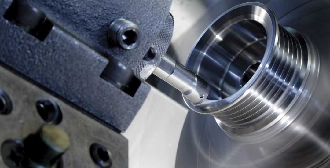
Before exploring how to measure threads, it is important to understand the key geometric elements that define a thread’s size, fit, and performance. These parameters form the basis of all subsequent measurement work.
Basic Thread Elements
- Major (Outside) Diameter: This is the largest diameter of an external thread and is measured across the crests.
- Minor (Root) Diameter: This represents the smallest diameter and is measured across the thread roots.
- Pitch Diameter (Effective Diameter): This is a theoretical diameter where the widths of the thread ridge and groove are equal, and it is a critical factor for determining fit.
- Pitch: This is the axial distance between adjacent threads measured along the pitch diameter.
- Thread Angle: This is the included angle formed between the flanks of a thread profile.
Measurement Approach
Thread measurement is generally conducted in stages. First, the operator identifies thread type and approximate size through visual inspection or preliminary tools. Next, the thread is measured using appropriate instruments such as micrometers, thread gauges, or projection systems to confirm dimensional accuracy. Environmental conditions must be controlled because temperature changes, surface contamination, and excessive measuring force can introduce error.
2. Common Tools for Measuring Threads
Before selecting a measurement method, it is important to understand the tools available, what they measure, and where each works best.
Basic Tools
| Tool | Main Use | Stärken | Einschränkungen |
| Thread Gauge (Pitch Gauge) | Pitch identification | Fast, inexpensive | Qualitative comparison, not numerical |
| Caliper/Micrometer | Major diameter | Easy to use | Cannot directly measure pitch diameter |
Thread pitch gauges identify standard pitches by direct comparison. Calipers and micrometers measure major diameters but require correct alignment and light measurement force.

Precision Instruments
| Instrument | Parameter | Genauigkeit | Vorteile | Best Use |
| Thread Micrometer | Pitch Diameter | ±0.004 mm | Direct reading | Batch inspection |
| Three-Wire Method | Pitch Diameter | ±0.001 mm | Highest precision | Gauge calibration, fine threads |
| Profile Projector / Optical Comparator | Profile, angle, pitch | ±0,005 mm | Visual profile evaluation | QC and first-article inspection |
| CMM / Thread Scanner | 3D full profile | ±0.001 mm | Automated, complete geometry | High-end manufacturing and R&D |
Modern CMMs and scanners capture the full 3D geometry for digital evaluation, deviation mapping, and traceable quality control.
Simple gauges work well for quick checks, but confirming fine tolerances relies on more advanced tools like thread micrometers or 3D scanning systems.
3. Measuring External Threads
External threads are typically evaluated through three key dimensions, like major diameter, pitch, and pitch diameter. Each measurement reflects different aspects of thread engagement, so the process should be carried out in sequence rather than performed as isolated checks.
Measuring Major Diameter
- Clean both thread surface and measuring contacts
- Use a micrometer or caliper within appropriate range
- Measure multiple positions and average results
- Maintain consistent pressure to avoid deformation
Measuring Pitch
- Direct method: use a pitch gauge and select the blade that fits perfectly without force
- High-accuracy method: use an optical microscope to measure several pitches and average the result
- Ink transfer inspection: imprint the thread onto paper and measure spacing after magnification
Measuring Pitch Diameter—Three-Wire Method
The three-wire method is widely recognized as the most accurate way to measure external thread pitch diameter.
Steps:
- Select three wires of correct diameter (optimal: d ≈ 0.57735P for 60° metric threads)
- Place two wires on one side and one wire on the opposite side
- Measure the over-wire dimension M using an outside micrometer
- Calculate pitch diameter using: For 60° metric threads: d₂ = M − 3d + 0.866P
Example Reference (Partial Metric Thread Table)
| Thread | Pitch P (mm) | Best Wired (mm) | M Value (Theoretical) |
| M6 | 1 | 0.577 | 6.325 |
| M8 | 1.25 | 0.722 | 8.37 |
| M10 | 1.5 | 0.866 | 10.414 |
| M12 | 1.75 | 1.01 | 12.459 |
| M16 | 2 | 1.155 | 16.533 |
Once all three measurements align with the specification, external threads can be validated with confidence rather than assumption.
4. Measuring Internal Threads

Measuring internal threads is inherently more difficult due to limited visibility and restricted access for measurement tools. Accurate inspection requires specialized gauges and precise techniques to evaluate fit and functional performance.
Thread Plug Gauge (Go/No-Go)
A plug gauge offers a fast and reliable way to verify internal threads:
- The GO end must screw in freely to the full depth of the thread.
- The NO-GO end must not enter more than 2.5 turns.
This check confirms whether a thread is acceptable or rejected, but it does not provide exact numerical dimensions.
Internal Thread Micrometer and Three-Ball Method
- Internal thread micrometers with hook-shaped anvils can measure the pitch diameter and minor diameter directly.
- For higher precision, the three-ball method is used. This technique is similar to the external three-wire method but adapted to the geometry of internal threads, providing accurate pitch diameter measurements.
Using these tools, internal threads can be evaluated precisely despite restricted access, ensuring they meet functional and tolerance requirements.
5. Thread Parameter Calculation and Tolerance Control
Once threads are measured, understanding how to calculate parameters and interpret tolerances is crucial for ensuring proper fit and performance in assemblies. Correct calculations help engineers and machinists confirm whether threads will function as intended.
Key Equations
- For metric threads, the pitch diameter can be approximated by the formula: d₂ = d − 0.6495P.
- The three-wire method uses M = d₂ + 3d − 0.866P to calculate pitch diameter for 60° threads.
- The optimal wire diameter for measurement can be calculated as d = P / (2 cos(α/2)), where α is the thread angle.
Thread Allowance and Fit Grades
- External threads use tolerance letters such as e, g, and h to indicate the position of the tolerance zone relative to the basic profile.
- Internal threads use G or H to indicate the tolerance position for the mating thread.
- Lower numerical grades, such as 4H or 4h, represent higher precision fits suitable for high-performance applications.
- Standard engineering fits for general mechanical assemblies are often 6H for internal threads and 6g for external threads.
Accurate parameter calculation and correct fit grade selection ensure that threads will mate as intended, preventing misalignment and mechanical interference during assembly.
6. Measuring Special Thread Types
Certain threads require additional attention due to their geometry, size, or material. Standard measurement methods may not be sufficient, so it is important to adjust techniques and tools for these special cases.
Pipe Threads (NPT/BSP)
Pipe threads are tapered, and their primary function is to create a seal. Measurement must account for taper angle, and functional verification typically includes a sealing test under pressure to ensure proper engagement.
Trapezoidal and Buttress Threads
These threads have unique flank angles, usually 30° for trapezoidal and 33°–45° for buttress threads. Measurement requires correction factors to account for the angle differences, particularly when determining pitch diameter and engagement fit.
Micro Threads (Less than 3 mm diameter)
Threads with very small diameters demand a microscope for visual inspection and micrometer measurement. Low measurement force is essential to avoid deformation, and precision handling ensures accurate readings.
Plastic Threads
Plastic threads are prone to distortion under measurement force. Non-contact or optical methods are recommended, and any contact measurements must use minimal pressure to preserve thread geometry.
Adjusting measurement techniques for these special threads ensures accuracy without compromising their function or material integrity.
7. Common Errors and How to Avoid Them
Thread measurement can be affected by a variety of factors, from environmental conditions to operator technique. Recognizing these common error sources and applying the correct preventive measures is essential for accurate and repeatable results.
| Error Source | Lösung |
| Temperature variation | Measure at 20°C or compensate expansion |
| Dirt or burrs | Clean with solvent and soft brush |
| Excess force | Use constant-pressure devices |
| Misalignment | Support with V-blocks ensures coaxial setup |
| Uncalibrated tools | Regular calibration schedule (gauges 6–12 months) |
Maintaining controlled temperature, clean threads, proper alignment, and calibrated tools directly prevents deviations in major, pitch, and pitch diameter measurements.
8. Modern Trends in Thread Measurement
Advances in technology are transforming how threads are measured, particularly in CNC machining and high-volume production. Modern systems focus on efficiency, accuracy, and traceability, allowing manufacturers to detect deviations early and maintain consistent quality.
- Inline inspection systems monitor thread dimensions directly during machining, providing immediate feedback to correct tool wear or setup deviations before parts leave the machine.
- Machine vision captures high-resolution images of threads at high speed, automatically analyzing pitch, profile, and flank angles to detect defects that are difficult to measure manually.
- Robot-assisted metrology improves repeatability by precisely positioning gauges or probes, reducing variability caused by human handling and alignment errors.
- 3D scanning and digital analysis generate complete point-cloud models of threads, enabling digital storage, reverse engineering, and comparison against CAD models to ensure tolerance compliance across batches.
Adopting automated and digital measurement technologies directly addresses the limitations of manual methods, improving reliability and traceability in threaded components.
Abschluss
Accurate thread measurement is critical for precision machining, where even minor deviations can affect assembly performance, component longevity, and overall system reliability. From high-tolerance automotive parts to finely threaded components in instrumentation, the choice of measurement methods and tools directly impacts manufacturing outcomes.
Aiming to maintain quality while scaling production? Consult a CNC machining provider like the Beska team that prioritizes both expertise and modern measurement technologies ensures that threads are consistently produced to specification and function reliably in demanding applications.
Tauchen Sie tiefer in unsere Ressourcen ein
Damit Sie einige aufschlussreiche Lektüre finden, haben wir eine Liste mit empfohlenen Artikeln speziell für Sie zusammengestellt:
 German
 English
 Hebrew
 Turkish
 French
 Russian
 Spanish
 Portuguese