


A shaft rotates inside a bearing. A gear is mounted onto a motor shaft. A bushing is pressed into a housing. Although these assemblies perform very different functions, they all rely on the same engineering principle: fit.
The fit between two mating parts determines how they assemble, how they move, and how they perform under load. A fit that is too loose may cause vibration, wear, or positioning errors. A fit that is too tight may create assembly problems, excessive stress, or premature component failure.
In this article, we’ll explain the three main types of fit used in engineering, from clearance fit and transition fit to interference fit. We’ll also discuss how to choose the right fit for different applications, common problems caused by incorrect fit selection, and the standards commonly used in manufacturing.
1. What Is Engineering Fit?

Engineering fit refers to the dimensional relationship between two mating components, most commonly a shaft and a hole.
When a shaft is inserted into a hole, neither part is manufactured to a single exact size. Instead, both are produced within specified tolerances. The relationship between these tolerances determines whether the parts assemble freely, require light force, or require a press fit.
In simple terms:
- If the hole is always larger than the shaft, a clearance fit is created.
- If the shaft is always larger than the hole, an interference fit is created.
- If the tolerance zones overlap, a transition fit is created.
Engineering fits are used to control movement, positioning accuracy, load transmission, and assembly behavior. Without proper fit selection, even a perfectly machined component may fail to function as intended.
2. Why Engineering Fits Matter in Mechanical Design
Engineering fits affect far more than assembly. The selected fit influences how components behave throughout the entire service life of a product. A poor fit can introduce problems that may not appear until after installation or long-term operation.
For example, excessive clearance may allow unwanted movement between parts. This movement can lead to vibration, noise, accelerated wear, and reduced positioning accuracy.
On the other hand, excessive interference can create assembly difficulties and introduce internal stresses that shorten component life.
Common problems caused by incorrect fit selection include:
- Premature bearing failure
- Excessive vibration during operation
- Difficult or inconsistent assembly
- Misalignment between components
- Reduced service life
- Increased maintenance requirements
In many cases, solving these issues does not require redesigning the entire product. Selecting a more appropriate fit is often enough to improve performance and reliability. Before choosing a fit, it’s important to understand the three primary categories used in engineering.
3. Clearance Fit: When Parts Need Free Movement

Among the three primary fit categories, clearance fits are the most widely used in mechanical engineering. They are designed for assemblies where components must rotate, slide, or move relative to one another without excessive resistance.
How It Works
A clearance fit exists when the hole is manufactured slightly larger than the shaft. Because a gap is always present between the two components, assembly can usually be completed without pressing or thermal methods.
The amount of clearance varies depending on the application. In precision assemblies, the gap may be kept small to improve guidance and reduce vibration. In other cases, larger clearances are intentionally used to simplify assembly or accommodate thermal expansion during operation.
Advantages of Clearance Fit
One reason clearance fits are so common is their practicality in production and maintenance.
- Easy assembly and disassembly
- Lower machining cost due to less restrictive tolerances
- Reduced assembly equipment requirements
- Suitable for components that must rotate or slide
- Simplified maintenance and replacement
For many general mechanical assemblies, clearance fits are the most economical option.
Limitations of Clearance Fit
Despite their advantages, clearance fits are not suitable for every application. Potential limitations include:
- Limited positional accuracy
- Inability to transmit torque directly
- Increased vibration under dynamic loads
- Potential wear caused by repeated movement
When accurate positioning or torque transmission is required, a different fit type may be more appropriate.
Typische Anwendungen
Clearance fits are commonly found in bearing assemblies, sliding shafts, bushings, and linear guide systems. In these applications, controlled movement is more important than rigid positioning.
For example, a rotating shaft inside a bearing requires sufficient clearance to allow smooth operation while accommodating lubrication and thermal expansion. Similarly, linear guide mechanisms often depend on carefully controlled clearance to balance movement and stability.
4. Transition Fit: Balancing Positioning Accuracy and Serviceability
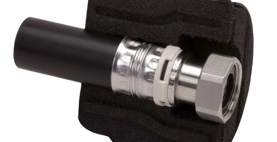
In many mechanical assemblies, engineers need more positioning accuracy than a clearance fit can provide, but do not want the permanent connection created by an interference fit. This is where transition fits are commonly used.
How It Works
A transition fit falls between a clearance fit and an interference fit. Depending on the actual dimensions of the mating parts, assembly may result in a very small clearance or a light interference. Some components can be assembled by hand, while others may require gentle tapping or light pressing.
Advantages of Transition Fit
Its unique characteristic makes transition fits particularly useful when accurate alignment is important, but future disassembly may still be required.
- Better positional accuracy than clearance fits
- Easier assembly than interference fits
- Reduced risk of component movement
- Possibility of future disassembly
- Suitable for precision assemblies
For many mechanical systems, transition fits offer an effective compromise between accuracy and serviceability.
Limitations of Transition Fit
However, transition fits are not suitable for every application. Because the final assembly condition depends on where the actual dimensions fall within the tolerance range, assembly consistency can vary from part to part.
In high-vibration environments or applications that require significant torque transmission, a transition fit alone may not provide enough holding force. Additional locking methods such as keys, pins, or retaining compounds are sometimes required.
Typische Anwendungen
Transition fits are widely used in precision mechanical assemblies where accurate positioning is critical. Common examples include dowel pins, bearing outer rings, shaft couplings, and various locating features used in automation equipment and industrial machinery.
For example, a bearing outer ring installed in a housing often uses a transition fit. The fit helps keep the bearing properly located while still allowing replacement during maintenance. Similarly, dowel pins frequently rely on transition fits to ensure repeatable alignment between mating components without creating a permanent assembly.
5. Interference Fit: Creating a Secure and Permanent Mechanical Connection

When components must remain firmly connected under load, vibration, or repeated operation, engineers often choose an interference fit.
How It Works
Unlike a clearance fit or transition fit, an interference fit is designed so that the shaft is slightly larger than the hole. Because the two components cannot be assembled freely, installation typically requires pressing, heating, cooling, or a combination of assembly methods.
Once assembled, the contact pressure between the mating surfaces creates a strong mechanical connection. This friction helps prevent relative movement and allows the assembly to transmit torque without relying on additional fasteners such as set screws, keys, or retaining rings.
Advantages of Interference Fit
Interference fits provide several important benefits:
- High positional stability
- Excellent torque transmission capability
- Vibrationsfestigkeit
- Elimination of additional fastening hardware
- Compact and reliable assembly design
For high-performance mechanical systems, interference fits are often preferred over set screws or other mechanical locking methods.
Limitations of Interference Fit
Interference fits also require greater attention during design and manufacturing. Potential challenges include the following:
- More difficult assembly
- Higher machining requirements
- Risk of damage during installation
- Reduced serviceability
- Greater sensitivity to thermal expansion
Engineers must also consider material properties, wall thickness, and operating temperature before specifying an interference fit.
Typische Anwendungen
Interference fits are widely used in applications such as gear hubs, motor shafts, pulley assemblies, bearing mounting locations, and press-fit bushings. These assemblies share a common requirement: maintaining a secure mechanical connection throughout the product’s operating life.
6. Clearance Fit vs Transition Fit vs Interference Fit
Although clearance fits, transition fits, and interference fits are all used to control the relationship between mating parts, they are designed to solve different engineering challenges. Some applications prioritize free movement and easy maintenance, while others require precise positioning or maximum holding strength.
The table below provides a side-by-side comparison of the three most common fit categories.
| Besonderheit | Clearance Fit | Transition Fit | Interference Fit |
| Assembly Force | Hand assembly | Light press or tapping | Press fit or thermal assembly |
| Relative Movement | Allowed | Limited | Keiner |
| Positioning Accuracy | Untere | Medium to high | Hoch |
| Torque Transmission | Poor | Limited | Exzellent |
| Manufacturing Cost | Untere | Mäßig | Höher |
| Serviceability | Easy to remove | Usually removable | Often difficult to remove |
| Typische Anwendungen | Bearings, sliding shafts | Dowel pins, couplings | Gear hubs, bushings |
Each fit type serves a different purpose. There is no universally “best” fit. The correct choice depends on how the assembly is expected to function.
7. How to Choose the Right Fit
Choosing the right fit involves more than selecting a tolerance class from a chart. Engineers need to consider how the assembly will function, how it will be assembled, and the conditions it will experience during operation.
Start with the Function of the Assembly
The first consideration is whether the mating parts need to move relative to each other. If rotation, sliding, or adjustment is required, a clearance fit is usually the best option. Bearings, guide shafts, and sliding mechanisms are common examples. If movement must be minimized, a transition fit or interference fit may be more suitable.
Consider the Loads Involved
The amount and type of load can also influence fit selection. Assemblies that must transmit torque or resist vibration often require a tighter fit. This is why gears, pulleys, and press-fit bushings commonly use interference fits. In contrast, assemblies that mainly guide movement can often operate effectively with a clearance fit.
Think About Assembly and Maintenance
A fit that performs well in operation should also be practical to assemble and service. Clearance fits are generally the easiest to install and remove. Transition fits offer a balance between positioning accuracy and serviceability. Interference fits provide the strongest connection but may require pressing, heating, or cooling during assembly and can be more difficult to remove later.
Consider the Operating Environment
Temperature can affect how a fit performs over time, especially when different materials are involved.
For example, aluminum and steel expand at different rates when heated. A fit that works well during assembly may behave differently once the product is operating. For applications exposed to significant temperature changes, thermal expansion should be considered during the design stage.
In most cases, fit selection is a balance between performance, manufacturability, and maintenance requirements. The best choice is the one that supports the intended function of the assembly without creating unnecessary production or service challenges.
8. Common Problems Caused by Incorrect Fit Selection
Even well-designed components can experience performance issues when the selected fit does not match the application. The following problems are frequently encountered in manufacturing and assembly.
Excessive Wear
When a clearance fit is larger than necessary, the mating components may move more than intended during operation. This repeated movement increases friction between the surfaces and gradually accelerates wear. As the components wear, the clearance becomes even larger, which can further reduce accuracy and shorten service life.
Assembly Difficulties
An overly tight fit can make assembly more difficult than expected. Components may require excessive force during installation, increasing production time and the risk of damaging shafts, housings, or other mating parts. In severe cases, the assembly process may need to be redesigned altogether.
Component Loosening
A fit that is too loose for the applied load may allow components to shift during operation. This is particularly common in applications exposed to vibration or repeated loading. Over time, the movement can lead to noise, reduced positioning accuracy, and premature component failure.
Cracking During Press Assembly
Interference fits rely on contact pressure between mating components, but excessive interference can create unwanted stress. Thin-wall housings, brittle materials, or poorly controlled assembly processes may lead to cracking or permanent deformation during installation. This is one reason why material selection and wall thickness should always be considered when specifying an interference fit.
Thermal Expansion Issues
Temperature changes can alter the relationship between mating parts. Components made from different materials often expand and contract at different rates, which may increase clearance or reduce interference during operation. A fit that performs well during assembly may behave very differently in a high-temperature environment if thermal expansion is not considered during the design stage.
Most fit-related problems can be avoided by evaluating the assembly requirements early in the design process. Considering factors such as movement, loading conditions, operating temperature, and maintenance requirements helps ensure that the selected fit continues to perform as intended throughout the product’s service life.
9. ISO Fit Classes and Standards
Once engineers decide whether a clearance fit, transition fit, or interference fit is required, the next step is selecting a specific fit class on the drawing.
This is where standards such as ISO 286 and ANSI B4.1 come into play. These systems provide a common language for defining the relationship between mating parts and help ensure that components manufactured by different suppliers will assemble as intended.
For most CNC-Bearbeitung projects, engineers will encounter fit designations such as H7/g6, H7/k6, and H7/p6. While the notation may appear complex at first, it simply defines the tolerance relationship between a hole and a shaft.
| Fit Designation | Typical Fit Type |
| H7/g6 | Clearance Fit |
| H7/k6 | Transition Fit |
| H7/p6 | Interference Fit |
The letters define the position of the tolerance zone, while the numbers define the tolerance grade.
Although these designations appear frequently on engineering drawings, designers should focus on the intended assembly function rather than simply copying commonly used fit combinations. The fit should always support the product’s performance requirements.
Abschluss
Choosing the right fit is ultimately about making sure components work together as intended. A fit that is too loose can lead to vibration, wear, and positioning issues, while a fit that is too tight can create assembly difficulties and unnecessary manufacturing costs.
Clearance fits are commonly used when movement is required. Transition fits help balance positioning accuracy and serviceability. Interference fits are typically selected when a secure mechanical connection is needed. The best choice depends on how the assembly will function, how it will be assembled, and the conditions it will experience during operation.
At Beska, many of the components we manufacture involve controlled fits, including bearing housings, motor shafts, gear assemblies, bushings, and precision locating features. During DFM review, we often evaluate fit requirements together with material selection, surface finishing, and assembly methods to help customers avoid problems later in production. If you’re working on a new product and need support with tolerance selection or precision machining, our engineering team is always happy to review your drawings and discuss possible manufacturing solutions.
Tauchen Sie tiefer in unsere Ressourcen ein
Damit Sie einige aufschlussreiche Lektüre finden, haben wir eine Liste mit empfohlenen Artikeln speziell für Sie zusammengestellt:
 German
 English
 Hebrew
 Turkish
 French
 Russian
 Spanish
 Portuguese