


Selecting the right CNC gear machining method has a direct impact on manufacturing cost, achievable quality, and production efficiency. Hobbing, shaping, milling, and grinding each have different capabilities, tolerance limits, and production characteristics. Many shops rely on the equipment they already have, but the same machining method is rarely the best choice for every gear.
The right process depends on the gear geometry, production volume, and quality requirements. A machining method that is well suited for a 300 mm ring gear used in a wind turbine may be unnecessarily expensive for a 20 mm pinion in a medical device. Choosing the wrong process can increase machining cost several times without improving performance.
This guide compares the four main CNC gear machining methods, explains where each process performs best, and highlights the key manufacturing considerations that influence process selection.
1. What Is CNC Gear Machining
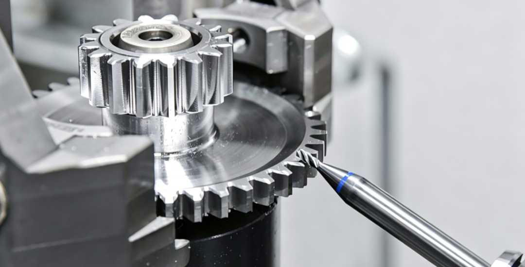
A gear drawing specifies parameters such as the module, pressure angle, helix angle, and AGMA quality class, but selecting the appropriate machining method is equally important. The manufacturing process must be capable of producing the required tooth geometry, accuracy, and surface quality.
CNC gear machining differs from conventional CNC-Fräsen or turning because it requires precise synchronization between the cutting tool and the workpiece. Each tooth must be indexed accurately as it is generated, otherwise the finished gear will not mesh correctly with its mating component. While a standard CNC machine may hold ±0.05 mm on a machined feature, gear machining demands that same level of control across every tooth on the gear.
This synchronization is achieved through coordinated control of the workpiece rotary axis and the cutting spindle. By adjusting the machining program, the same equipment can produce spur gears, helical gears, splines, and worm gears with different tooth counts and geometries, providing much greater flexibility than traditional mechanically driven gear cutting machines.
2. Main Machining Methods: Hobbing, Shaping, Milling, and Grinding
Each gear machining method has different strengths, limitations, and ideal applications. The best choice depends on the gear geometry, production volume, material, and required quality level rather than the machining method itself.
Hobbing: High-Volume Production for External Spur and Helical Gears
A hob is a cylindrical cutting tool with helical teeth. During machining, the hob and the gear blank rotate in precise synchronization while the hob feeds across the workpiece. This continuous generating motion produces the involute tooth profile.
Hobbing is the fastest and most efficient method for manufacturing external spur and helical gears in medium to high production volumes. Small gears can often be machined in less than one minute, making hobbing the preferred choice for automotive transmission gears, industrial gearboxes, and other high-volume applications.
Shaping: Internal Gears and Gears with Shoulders or Flanges
A gear shaping cutter resembles a gear with cutting edges on its face. It reciprocates while rotating in synchronization with the gear blank, gradually removing material to generate the tooth profile.
Shaping is well suited for internal gears and external gears with shoulders or flanges that prevent a hob from passing through the workpiece. Although the process is typically two to three times slower than hobbing and produces a slightly rougher surface finish, it remains the preferred solution for planetary gear sets, clutch components, and other complex gear geometries.
Milling (5-Axis): Flexible for Prototypes and Low-Volume Production
Five-axis milling machines use an end mill or disc cutter to machine each tooth space individually. The cutting tool can tilt to match the helix angle, allowing a wide variety of gear geometries to be produced without dedicated gear-cutting tools.
Because each tooth is machined separately, cycle times are significantly longer than hobbing. A gear that can be hobbed in 45 seconds may require 8–10 minutes on a five-axis machining center. For this reason, five-axis milling is generally reserved for prototypes, repair work, large custom gears, and low-volume production rather than mass manufacturing. Many job shops also use five-axis machining for gear repair because it eliminates the need for dedicated hobs or shaping cutters.
Grinding: Finishing Hardened Gears for High Precision and Low Noise
Gear grinding is typically performed after heat treatment using a vitrified or CBN grinding wheel. The grinding wheel removes a small amount of material to correct heat-treatment distortion while improving tooth accuracy and surface finish.
Among the four machining methods, grinding provides the highest dimensional accuracy and the best surface finish. It is also the slowest and most expensive process, so it is usually reserved for finishing operations rather than rough machining. Grinding is commonly used for aerospace transmission gears, electric vehicle drivetrains, precision machine tools, and other applications requiring high accuracy, low noise, and excellent running performance.
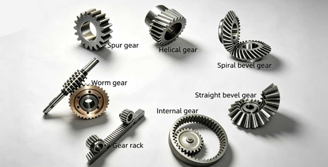
No single machining method is suitable for every gear. Gear geometry, production volume, material, and quality requirements should be evaluated together to select the most appropriate manufacturing process.
3. Key Performance Indicators: AGMA Class, Surface Finish, Runout, and Pitch Error
Different gear machining methods produce different levels of accuracy, surface quality, and manufacturing cost. To evaluate these differences consistently, manufacturers use standardized quality indicators such as AGMA quality class, surface finish, runout, and pitch and profile error. These specifications determine how smoothly a gear runs, how much noise it generates, and whether it meets the performance requirements of its application.
Indicator | What It Measures | Typical Range | What It Affects |
|---|---|---|---|
AGMA Quality Class | Overall gear accuracy (Q3 to Q15) | Q8 to Q11 for hobbing; Q13 and above for grinding | Cost and application. Q8 for general industrial use. Q12 for automotive. Q14 and above for aerospace. |
Surface Finish (Ra) | Smoothness of the tooth flank | Ra 1.6–3.2 µm for cut gears; Ra 0.4 µm or better for ground gears | Noise and wear. High-speed gears need smoother finish to reduce friction. |
Runout | Deviation of teeth from true center | Typically below 0.05 mm for automotive gears | Vibration. High runout causes gear noise and shortens bearing life. |
Pitch and Profile Errors | Tooth spacing and flank shape accuracy | Measured in microns; tolerance depends on AGMA class | Mesh smoothness. Errors cause whine, clatter, and uneven load distribution. |
Among these indicators, AGMA quality class is usually the primary specification because it defines the allowable limits for multiple gear accuracy parameters. Higher AGMA classes require tighter control of runout, pitch accuracy, and surface finish, resulting in longer machining time, more demanding inspection, and higher manufacturing cost. The required quality level should match the operating speed, load, and application rather than being specified higher than necessary.
Sources: AGMA 2000-A88 Gear Classification and Inspection Handbook; Machinery’s Handbook, 30th Edition.
Note: The values shown are typical industry ranges. Actual achievable results depend on the machining method, machine condition, tooling, workholding, material, and heat treatment.
4. Advantages and Limitations of CNC Gear Machining
CNC gear machining offers greater flexibility and process control than conventional mechanically driven gear-cutting equipment, but it is not the best solution for every application. The most suitable process depends on production volume, gear geometry, quality requirements, and manufacturing cost.
Advantages of CNC Gear Machining
Faster Changeovers
Conventional gear-cutting machines often require mechanical change gears or dedicated setup adjustments when switching between different gear designs. CNC machines perform the same change through the machining program, reducing setup time and improving production flexibility, especially for small- and medium-volume production.
Flexible for Prototypes and Low-Volume Production
CNC-controlled gear cutting and five-axis machining can produce a wide range of gear geometries without dedicated mechanical setups. This flexibility makes CNC machining well suited for prototypes, replacement parts, custom gears, and low-volume production where frequent design changes are common.
Easy Integration with Automated Production
Modern CNC gear machines can be integrated with automatic loading systems, robotic handling, and in-process measurement, allowing stable, repeatable production with minimal operator intervention.
Limitations of CNC Gear Machining
Higher Cost for High-Volume Production
For large production runs of identical gears, dedicated gear-cutting equipment often provides lower per-part costs because setup time is distributed across a large number of components. CNC gear machining delivers greater flexibility but is not always the most economical choice for mass production.
Longer Cycle Time for Certain Applications
Processes such as five-axis milling machine each tooth individually, making them considerably slower than hobbing for large gears or high-volume production. The increased flexibility comes at the expense of machining efficiency.
Greater Programming and Setup Requirements
CNC gear machining requires specialized knowledge of gear geometry, cutter selection, machine synchronization, and inspection requirements. Compared with conventional CNC machining, programming and setup are generally more complex and demand greater operator experience.
No single manufacturing method is ideal for every gear. Selecting the right process requires balancing production volume, gear geometry, required quality, manufacturing efficiency, and overall cost.
5. Method Comparison: Hobbing, Shaping, Milling, and Grinding
Each gear machining method offers different advantages in terms of accuracy, productivity, flexibility, and manufacturing cost. Comparing them side by side makes it easier to select the most suitable process for a specific application.
Dimension | Hobbing | Shaping | Milling (5-axis) | Schleifen |
|---|---|---|---|---|
Typical Quality & Finish | AGMA Q8-Q11, Ra 1.6–3.2 µm | AGMA Q8-Q10, Ra 1.6–3.2 µm | AGMA Q9-Q11, typical milled finish | AGMA Q13+, Ra 0.4 µm or better |
Cost Level | Low equipment, low tooling | Medium equipment, low tooling | High equipment, medium tooling | Very high equipment, high tooling |
Rüstzeit | Medium | Medium | Niedrig | Hoch |
Cycle Time | Schnell | Medium | Slow | Very slow |
Machining Difficulty | Medium skill | Medium skill | High skill, complex programming | High skill, wheel dressing |
Typical Application | Automotive gears, gearboxes | Planetary gears, internal gears | Prototypes, repair, robotics | Aerospace, EV, high-speed gears |
As a general guideline, hobbing is the preferred choice for high-volume external gears, shaping is best suited for internal gears and restricted geometries, five-axis milling provides the greatest flexibility for prototypes and custom parts, and grinding is typically reserved for finishing operations requiring the highest accuracy and surface quality.
Sources: AGMA 2000-A88 Gear Classification and Inspection Handbook; Machinery’s Handbook, 30th Edition.
Note: Values shown are typical industry ranges. Actual performance depends on machine condition, tooling, workholding, material, and heat treatment.
6. Manufacturing Considerations for CNC Gear Machining
Achieving consistent gear quality depends on more than selecting the right machining method. Machine setup, workholding, thermal stability, tool wear, and heat treatment all influence the final gear accuracy. Controlling these factors throughout production is essential for maintaining dimensional consistency and reducing scrap.
Machine Setup and Tolerance Control
Accurate workholding is the foundation of successful gear machining. The workpiece should be located from the functional bore or reference diameter to minimize runout and maintain concentricity throughout machining. For higher AGMA quality levels, even small setup errors can affect the final tooth geometry.
Machine warm-up is equally important. As the spindle, bearings, and machine structure reach operating temperature, thermal expansion changes the relative position of the cutting tool and the workpiece. Allowing the machine to stabilize before production helps reduce dimensional drift between the first and last parts in a production run.
When gears require heat treatment followed by grinding, sufficient grinding stock should be left on the tooth flanks. This allows distortion introduced during hardening to be removed during the finishing process while maintaining the required tooth geometry.
Tool Wear and Process Stability
Tool condition directly affects gear accuracy and surface finish. As cutting tools wear, tooth dimensions gradually change and surface quality deteriorates. Regular tool inspection and timely replacement help maintain stable production and reduce dimensional variation.
Process stability also depends on maintaining consistent machining conditions. Changes in coolant temperature, cutting parameters, or machine loading can influence dimensional accuracy during long production runs. Stable machining conditions produce more consistent gear quality.
Common Manufacturing Risks
- Pitch Error is often associated with synchronization problems between the cutting tool and the workpiece. Encoder faults, drive system issues, or machine wear can gradually increase tooth spacing errors and should be investigated as soon as abnormal inspection results appear.
- Thin-walled gears are susceptible to deformation during clamping. Proper fixture design and controlled clamping forces help minimize distortion while maintaining sufficient rigidity for machining.
- Heat treatment distortion is another common source of dimensional variation. Changes in tooth geometry after hardening should be anticipated during process planning by leaving adequate grinding allowance and verifying the first parts from each heat treatment batch.
Recommended Manufacturing Practices
Consistent gear quality comes from a stable manufacturing process rather than any single machining operation. Warm up the machine before production, use appropriate workholding, monitor tool wear regularly, maintain stable machining conditions, and inspect the first parts of every production batch before continuing with full-scale machining. These practices help improve dimensional consistency, reduce rework, and maintain reliable gear quality throughout production.
7. Design Considerations for CNC Gear Machining
Small changes to a gear drawing can have a significant impact on machining time, tooling, and inspection. Effective gear design considers not only functional performance but also how the gear will be manufactured, inspected, and finished.
Design Features That Affect Machining
Gear geometry directly influences tool accessibility and process selection. Internal gears, small-module gears, and tight root geometries often require specialized machining methods and smaller cutting tools. To reduce machining difficulty and minimize the risk of tool damage, the root radius should be compatible with standard gear-cutting tools. A common design guideline is to specify a root radius of at least 0.1 × module, unless the application requires otherwise.
Match Tolerances to Inspection Methods
Tolerance requirements should reflect how the gear will be inspected. Runout, pitch error, and profile error are verified using different inspection methods and fixtures. Using the same functional datum for both machining and inspection helps avoid measurement discrepancies and improves the consistency of quality control.
Provide Clear Drawing Requirements
Gear drawings should clearly define features that affect manufacturing and inspection, including root radius tolerances, case depth inspection locations, finished surfaces, and areas that must remain protected during grinding or heat treatment. Clear callouts reduce engineering questions and help prevent unnecessary rework during production.
Well-designed gear drawings balance performance, manufacturability, and inspectability. Considering these factors early in the design stage helps improve machining efficiency, inspection accuracy, and overall product quality.
8. Material Selection and Process Recommendations
Material selection influences not only gear strength and durability but also the machining process, heat treatment, achievable accuracy, and overall manufacturing cost. Choosing the appropriate material helps determine the most efficient manufacturing route for a specific application.
Material | Typical Application | Recommended Process |
|---|---|---|
4140/4340 (pre-heat treated) | General industrial gears | Hob or shape, grind if needed |
8620 (carburizing grade) | Automotive transmissions | Hob or shape, carburize, grind |
9310 (aerospace grade) | High-load aerospace gears | Hob, carburize, grind |
6061/7075 aluminum | Light-duty gears, prototypes | Hob or 5-axis mill |
Material hardness also affects machining strategy. Steels above approximately 30 HRC generally require carbide tooling, while stainless steels tend to work-harden during machining and benefit from stable cutting conditions that minimize excessive tool wear.
Material selection influences more than mechanical properties. It also determines the heat treatment process, machining sequence, tooling requirements, and the amount of finishing required after hardening. A material with a lower purchase price may ultimately increase manufacturing cost if it requires additional machining or finishing operations.
When heat treatment is part of the manufacturing process, expected distortion should be considered during process planning. Estimating material movement in advance helps determine the appropriate grinding allowance and improves dimensional consistency after hardening.
Abschluss
Choosing the right gear machining method is about matching the process to the application. Gear geometry, production volume, required accuracy, and material all influence the best manufacturing route. Selecting a more complex process or a higher AGMA class than necessary often increases cost without improving performance.
At Beska, we review every gear design from both a manufacturing and inspection perspective before production begins. By selecting the right machining process from the start, we help customers reduce machining costs, improve quality, and avoid unnecessary production issues.
 German
 English
 Hebrew
 Turkish
 French
 Russian
 Spanish
 Portuguese