


No manufacturing process produces perfectly identical parts. Tool wear, temperature changes, material behavior, and fixturing can all introduce small variations during production. Engineering tolerance defines how much variation is acceptable while allowing a part to function and assemble as intended.
For example, if a drawing specifies a 50 mm shaft, the finished part will not always measure exactly 50.000 mm. Tolerance defines the acceptable dimensional range. This becomes especially important for mating parts, where too little or too much clearance can lead to assembly or performance problems.
This guide explains what engineering tolerance is and how it affects dimensional control, fits, CNC-Bearbeitung, inspection, and manufacturing cost.
1. Why Engineering Tolerance Matters in Manufacturing
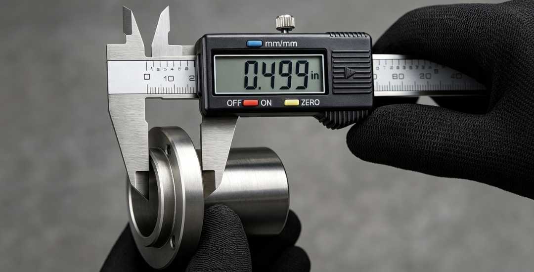
Engineering tolerances define acceptable variation so that manufactured parts can fit, function, and be inspected consistently. They are especially important in production, where components made at different times or in different batches need to assemble without individual fitting.
Correctly specified tolerances help control several important aspects of a part:
- Fit and assembly: Mating features assemble with the intended clearance or interference.
- Motion and alignment: Sliding, rotating, and locating features maintain the relationships required by the design.
- Production consistency: Clear acceptance limits make manufacturing and inspection more consistent and help reduce unnecessary rework.
Tolerance also affects manufacturing costs. Tighter requirements may require more controlled machining, additional finishing operations such as grinding or honing, and more demanding inspection. Tolerances that are unnecessarily tight can therefore increase cost and lead time without improving the function of the part.
A practical approach is to use tighter tolerances where function requires them and allow more variation on non-critical features.
2. Types of Engineering Tolerances
Engineering tolerances can control both the size of a feature and its geometric relationship to other features. The two main categories commonly encountered on mechanical drawings are dimensional tolerances and geometric tolerances.
Maßtoleranzen
Dimensional tolerances define the acceptable variation in feature size, such as length, diameter, width, and thickness. They can be expressed as bilateral tolerances, unilateral tolerances, or limit dimensions.
For example, a shaft specified as:
- Nominal diameter: 10.00 mm
- Tolerance: ±0.05 mm
- Acceptable range: 9.95–10.05 mm
Any measured diameter within this range meets the stated size requirement.
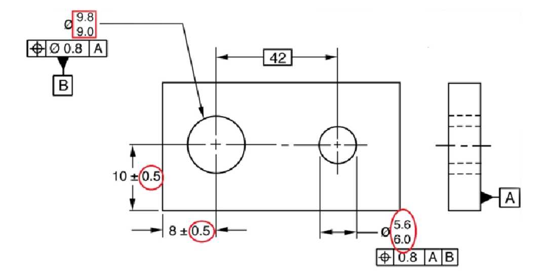
Dimensional tolerances help ensure that parts produced at different times or in different batches remain consistent and interchangeable.
Geometric Tolerances (GD&T)
Dimensional accuracy alone does not fully define part geometry. Geometric Dimensioning and Tolerancing (GD&T) controls the allowable variation in a feature’s form, orientation, location, or runout.
Common geometric controls include:
- Form: Flatness, straightness, circularity, and cylindricity
- Orientation: Parallelism, perpendicularity, and angularity
- Location: Position
- Runout: Circular runout and total runout
These controls are useful when the relationship between features matters more than their individual dimensions. For example, a mounting hole may have the correct diameter but still cause assembly problems if its position relative to the datum features is incorrect.
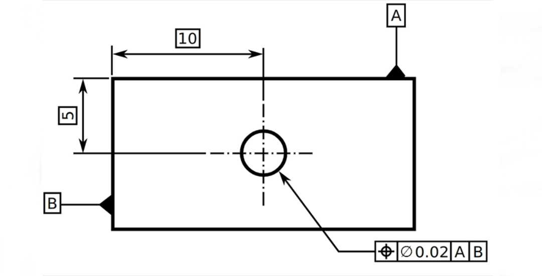
GD&T can also use material condition modifiers such as Maximum Material Condition (MMC) and Least Material Condition (LMC) where the allowable geometric variation depends on feature size.
Surface Finish Requirements
Surface finish is not a dimensional or geometric tolerance, but it is another important requirement commonly specified on engineering drawings. Surface roughness can affect friction, sealing, wear, appearance, and the performance of mating surfaces.
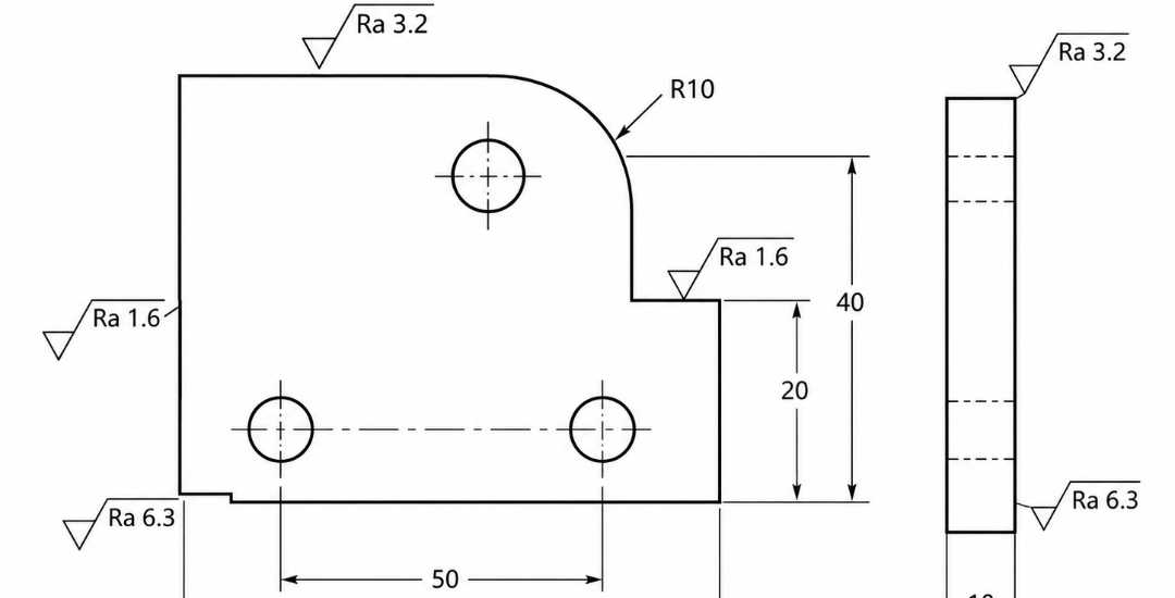
Requirements are commonly expressed using parameters such as Ra. The appropriate value depends on the function of the surface rather than the overall precision level of the part. Bearing seats, sealing surfaces, and sliding features may require different finishes from non-functional external surfaces.
Surface treatments and finishing operations can also change the final surface condition, so the required finish should be considered together with the manufacturing and post-processing method.
Together, dimensional tolerances, GD&T, and surface finish requirements define different aspects of how a finished part must be manufactured and inspected.
3. Engineering Tolerance Standards: ISO 2768 and ASME Y14.5
Engineering drawings often reference established standards so that designers, manufacturers, and inspectors interpret tolerance requirements consistently. ISO and ASME standards are among the commonly used systems in mechanical engineering.
ISO 2768
ISO 2768-1 specifies general tolerances for linear and angular dimensions when individual tolerances are not shown on the drawing. It defines four tolerance classes: fine (f), medium (m), coarse (c), and very coarse (v), with allowable variation depending on the nominal dimension.
A drawing may reference a general tolerance class in the title block, such as ISO 2768-m, while dimensions requiring different control can be toleranced individually.
The former ISO 2768-2, which covered general geometrical tolerances, has been withdrawn and replaced by ISO 22081:2021 for general geometrical and size specifications.
ASME Y14.5
ASME Y14.5 is widely used for dimensioning and Geometric Dimensioning and Tolerancing (GD&T). It establishes symbols, rules, definitions, and practices for communicating requirements related to size, form, orientation, location, profile, and runout.
The current edition, ASME Y14.5-2018 (R2024), provides a common framework for designers, manufacturers, and inspectors to interpret engineering drawings consistently.
Tolerance standards provide a shared drawing language, but the applicable standard and revision should always be clearly identified on the engineering drawing.
4. Engineering Tolerance in CNC Machining
CNC machining can achieve tight dimensional control, but the practical tolerance depends on part geometry, material, feature size, fixturing, machining process, and inspection method. A tolerance that is straightforward on one feature may be more difficult or costly on another.
Typical Tolerance Considerations by Machining Process
Different machining processes offer different advantages when tighter dimensional control is required.
| Machining Process | Typical Use | Tolerance Consideration |
| CNC-Fräsen | Brackets, housings, plates, complex features | Tight tolerances are achievable on critical features, but capability depends strongly on setup, geometry, and feature accessibility |
| CNC-Drehen | Shafts, sleeves, cylindrical parts | Well suited to controlling diameters, concentric features, and other rotational geometry |
| Boring / Reaming | Precision holes and bearing bores | Often used after initial machining when tighter bore size and consistency are required |
| Schleifen | Shafts, bearing surfaces, precision mating features | Useful when tighter dimensional control or finer surface finish is required after machining |
At Beska, ±0.01 mm is commonly achievable for CNC-machined features, while tolerances down to ±0.005 mm can be supported on selected critical features, depending on material, geometry, feature size, and inspection requirements.
Tighter tolerances may require additional finishing passes, more controlled fixturing, temperature management, and more detailed inspection. Applying the same tight tolerance to every feature can therefore increase manufacturing cost without improving part function.
The tightest tolerance is not always the most important one. Precision should be concentrated on features that directly affect fit, alignment, motion, or assembly.
5. Types of Fits: Clearance, Interference, and Transition
In mechanical assemblies, the tolerances of mating features determine how tightly the parts fit together. Depending on the selected tolerance zones, the result may be a clearance fit, an interference fit, or a transition fit.
Clearance Fit
A clearance fit maintains a gap between mating parts, with the shaft remaining smaller than the corresponding hole within the specified tolerance limits. This allows relative movement and makes assembly or disassembly easier, which is useful for sliding shafts, guide bushings, removable pins, and other components that need controlled movement.
Interference Fit
An interference fit occurs when the shaft is larger than the mating hole within the specified fit limits. Assembly usually requires pressing or controlled heating or cooling of the components. The resulting interference creates a secure mechanical connection, making this type of fit suitable for press-fit pins, hubs, sleeves, and similar components that should remain firmly positioned during operation.
Transition Fit
A transition fit falls between clearance and interference fits. Depending on the actual dimensions of the mating parts, the assembly may have a small clearance or a small interference. It is often used where accurate positioning is important but a heavy press fit is unnecessary, such as certain locating components, hubs, and couplings.
ISO Tolerance Grades and Fits
ISO 286 provides a standardized system for specifying tolerances and fits for holes and shafts. IT grades define the width of the tolerance zone, while letter designations define its position relative to the nominal size.
For example, combinations such as H7/g6, H7/h6, and H7/p6 produce different fit conditions even when the nominal hole and shaft sizes are the same. The required fit therefore depends on the tolerance zones of both mating features, not simply their nominal dimensions.
6. How Tolerances Affect CNC Machining Cost
Tighter tolerances can increase CNC machining cost, but the relationship is not proportional. The actual cost impact depends on the feature, material, part geometry, machining process, production volume, and inspection requirements.
As tolerance requirements become more demanding, manufacturers may need to introduce:
- Additional finishing passes or secondary operations
- More controlled fixturing and setups
- Specialized tooling or processes such as reaming, honing, or grinding
- More frequent in-process inspection
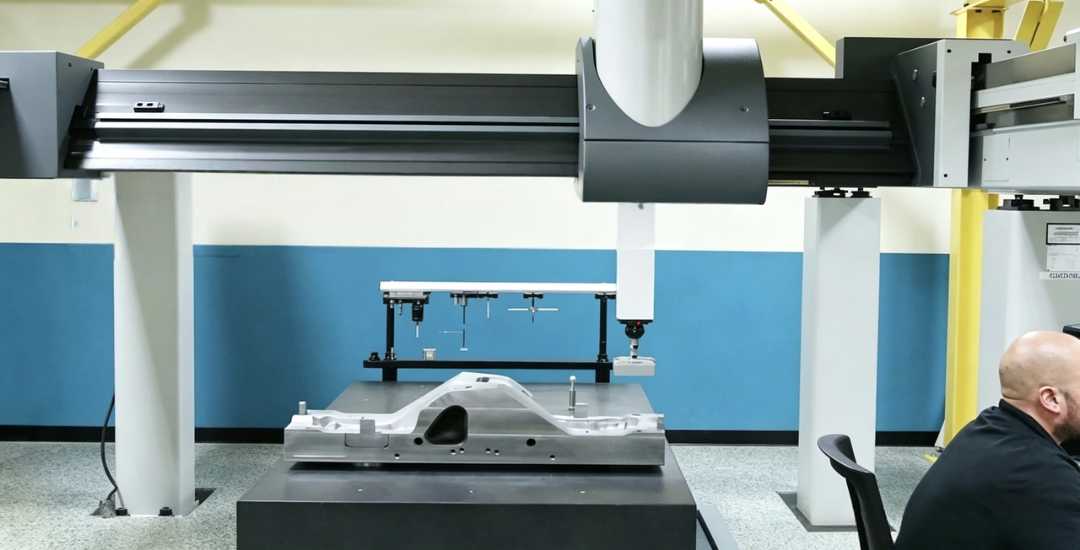
- More capable measuring equipment for final verification
For example, a non-critical clearance feature may be produced directly during standard milling, while a tightly controlled bearing bore may require boring or reaming followed by more detailed inspection. The additional cost comes from the process needed to produce and verify the feature consistently, not simply from the tolerance value itself.
For this reason, tight tolerances should be concentrated on dimensions that directly affect fit, alignment, motion, sealing, or other functional requirements. Non-critical features can often use broader general tolerances without affecting part performance.
Reviewing tolerance requirements during the design stage can reduce unnecessary machining and inspection costs while keeping critical features under the required control.
7. Tolerance Stack-Up: The Cumulative Effect
Tolerance stack-up describes how individual dimensional variations combine in an assembly. Even when every component is within its specified tolerance, the accumulated variation can still affect the final fit or overall dimension.
For example, consider three plates stacked together, each measuring 10 mm ±0.1 mm. The total stack height can range from 29.7 mm to 30.3 mm, giving an overall variation of ±0.3 mm. If that stack must fit within another tightly controlled feature, the accumulated tolerance becomes an important design consideration.
Tolerance stack-up analysis helps engineers determine whether these combined variations could create assembly or functional problems. Two common approaches are:
- Worst-case analysis: Evaluates the maximum possible variation when individual tolerances accumulate in the same direction.
- Statistical analysis: Estimates assembly variation based on the expected distribution of individual component dimensions.
The appropriate method depends on the application, production process, and acceptable level of risk. The important point is that a part can meet its own drawing tolerance and still contribute to an assembly that falls outside the required limits.
Abschluss
Engineering tolerance connects design requirements with what can be consistently manufactured and inspected. The right tolerance should reflect the function of each feature, with tighter control applied where fit, alignment, motion, sealing, or assembly depends on it.
For CNC-machined parts, tolerance decisions also affect process selection, inspection requirements, and production cost. Considering these factors early in the design stage can help avoid unnecessary machining complexity while keeping critical features under proper control.
At Beska, we work with OEM engineering teams to review part geometry, tolerance requirements, and manufacturability before production. Send us your drawings or CAD files for a DFM review and quotation.
 German
 English
 Hebrew
 Turkish
 French
 Russian
 Spanish
 Portuguese