


Chamfers are common edge features on CNC-machined parts. They are used to remove sharp edges, improve assembly lead-in, protect exposed corners, and make parts easier to handle. A small change in chamfer size or angle can also affect nearby dimensions, thread entry, contact surfaces, or thin-wall features.
The right chamfer depends on what the edge needs to do. A general 45° chamfer may work well for deburring or assembly, while smaller edge breaks, custom angles, or radiused edges may be more appropriate in other situations. Part tolerance, assembly direction, load, and machining access all need to be considered before the chamfer is added to the drawing.
1. What Is a Chamfer in CNC Machining?
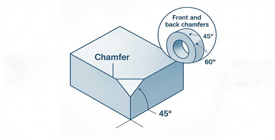
A chamfer is a flat, angled surface created by removing material from a sharp edge or corner. On CNC-machined parts, chamfers are commonly added to break sharp edges, remove burrs, provide assembly lead-in, and protect exposed corners during handling.
Chamfers can be machined on external edges, hole entrances, shafts, and other features where a sharp intersection is not desirable. Their size and angle depend on the function of the edge, the surrounding geometry, and the dimensional requirements of the part.
A chamfer is different from a fillet or edge radius because it creates a flat surface rather than a curved transition. That distinction becomes important when the edge is used for assembly guidance, thread entry, or stress-sensitive features.
2. Chamfer vs Bevel vs Fillet
Chamfers, bevels, and fillets can all change a sharp edge, but they are not the same feature. The main difference is the geometry they create and the job that edge needs to perform.
Chamfer
A chamfer removes the sharp corner and replaces it with a flat angled surface. In CNC machining, chamfers are commonly used for deburring, assembly lead-in, thread entry, and edge protection.
A 45° chamfer is common because it is easy to specify and machine, but chamfers can also use other angles when the part needs a particular clearance or insertion direction.
Bevel
A bevel is a broader term for an inclined surface along an edge. In some applications, the geometry may look very similar to a chamfer, which is why the two terms are sometimes used interchangeably.
The word bevel is more often used when the angled surface is a larger part of the component geometry, such as an edge prepared for welding or a structural transition. When the exact geometry matters, the drawing should define the angle and linear dimensions instead of relying on the term alone.
Fillet
A fillet creates a curved transition rather than a flat angled face. This makes it different from both a chamfer and a bevel.
Rounded transitions are often used where reducing local stress concentration, improving fatigue behavior, or creating smoother contact is more important than providing a straight lead-in edge. The required radius still depends on the part geometry, loading, and available machining access.
The simplest way to distinguish them is by shape: a chamfer or bevel creates a flat angled surface, while a fillet creates a radius. The function of the edge then determines which feature is more appropriate.
3. Common Types of Chamfers
Chamfers can vary in size, angle, and purpose. The most common forms in CNC machining include standard 45° chamfers, custom-angle chamfers, small edge breaks, and chamfers used at hole or thread entrances.
Standard 45° Chamfer
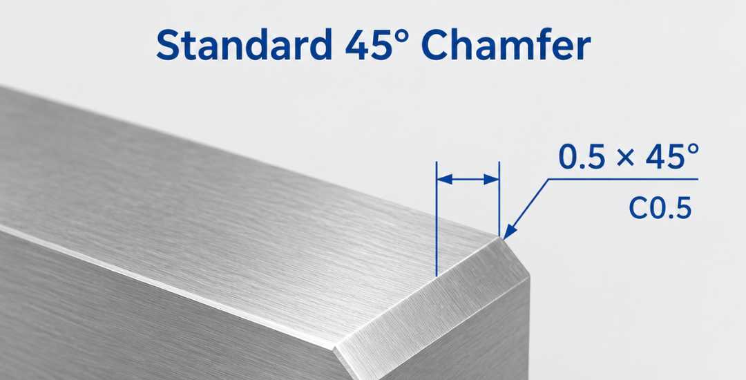
The 45° chamfer is the most common general-purpose form. It is frequently used to break sharp edges, remove burrs, and provide a simple lead-in for assembly.
On engineering drawings, a 45° chamfer may be shown as a callout such as C0.5 in some drawing conventions, or written explicitly as 0.5 × 45°. The drawing standard used for the project should define the final notation.
Because the geometry is simple, 45° chamfers are usually easy to machine with standard chamfering tools.
Custom-Angle Chamfer
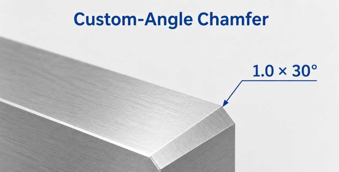
Not every chamfer needs to be 45°. Angles such as 30° or 60° may be used when the edge has a specific assembly, clearance, or mating requirement.
These chamfers should be dimensioned clearly on the drawing because angle and linear size both affect the final geometry. Their machining difficulty depends more on accessibility, tooling, and tolerance than on the fact that the angle is non-standard.
Small Chamfer or Edge Break
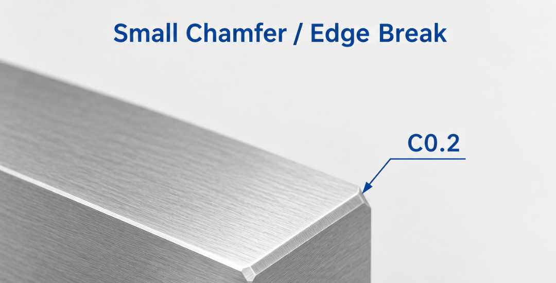
A small chamfer is often added where the goal is simply to remove a sharp edge without noticeably changing the surrounding geometry.
This is useful on precision features, thin sections, or cosmetic surfaces where a larger chamfer would remove too much material. The required size should be tied to the function of the edge rather than to a fixed definition of “micro chamfer.”
Hole and Thread-Entry Chamfer
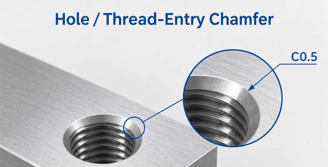
Chamfers are commonly added at drilled and tapped hole entrances to remove burrs and provide a smoother lead-in for pins, screws, or fasteners.
For threaded holes, the chamfer should be large enough to clean up the entrance without unnecessarily reducing effective thread engagement. The size should therefore be selected according to the thread and assembly requirements rather than from one universal chamfer range.
4. How to Choose a Chamfer
The chamfer should match the job that the edge needs to do. Edge protection, assembly guidance, thread entry, surrounding wall thickness, and dimensional tolerance all affect the final size and angle.
For General Edge Breaking
A small 45° chamfer is often sufficient when the goal is simply to remove a sharp edge or burr. It provides a clean edge without removing more material than necessary.
Larger chamfers are not always better, especially near thin walls, narrow lands, or dimensions that need to remain tightly controlled.
For Assembly Lead-In
Chamfers are commonly used to guide shafts, pins, screws, and mating parts during assembly. A standard 45° chamfer works well in many cases, while a custom angle may be useful when the insertion direction or mating geometry requires a different lead-in.
The chamfer should provide enough guidance without taking too much material away from the locating or contact surface.
For Holes and Thread Entrances
A chamfer at the entrance of a drilled or tapped hole can remove burrs and make it easier to start a pin, screw, or fastener.
For threaded holes, the chamfer should be large enough to clean the opening but not so large that it unnecessarily reduces effective thread engagement.
For Thin-Wall and Tight-Tolerance Features
Small edge breaks are often more suitable near precision diameters, sealing faces, thin walls, or other sensitive features. In these areas, the goal is usually to remove the sharp edge while preserving as much of the functional geometry as possible.
The required chamfer should therefore be defined from the actual tolerance and surrounding geometry rather than copied from a general edge note.
When a Radius Is a Better Choice
A chamfer is not always the best edge treatment. Where fatigue, repeated contact, or local stress is more important than assembly lead-in, a radius or fillet may be more appropriate.
The choice between a chamfer and a radius should be based on the function of the edge rather than treating both as interchangeable features.
5. How to Specify Chamfers on Engineering Drawings
A chamfer callout should make the required edge geometry clear without forcing the machinist to guess the size, angle, or location. The amount of detail needed depends on whether the chamfer is a general edge break or a functional feature.
Specify the Size and Angle Clearly
For a 45° chamfer, drawings may use a shorthand such as C0.5 where that convention is defined, or an explicit callout such as 0.5 × 45°.
For chamfers at other angles, both the linear dimension and angle should be shown clearly. A note such as 1.0 × 30° avoids ambiguity and makes the intended geometry easier to inspect.
Use General Edge Notes Carefully
A general note such as “Break sharp edges” can be useful for non-critical edges, but it may be too vague when edge size affects fit, wall thickness, sealing surfaces, or appearance.
Where a chamfer has a functional purpose, it is better to dimension that edge individually rather than rely on a general drawing note.
Identify Critical and Threaded Features
Chamfers near precision fits, sealing surfaces, thin walls, or mating features should be specified locally so the finished edge does not interfere with the required geometry.
Thread-entry chamfers also deserve separate attention. The callout should provide enough lead-in to remove burrs and help fastener engagement without removing more effective thread length than necessary.
6. Common Chamfer Design Mistakes
Small edge features can create machining or assembly problems when their size, angle, or purpose is not defined clearly on the drawing.
Oversized Chamfers on Critical Edges
A chamfer that is larger than necessary can remove useful material from thin walls, narrow lands, sealing surfaces, or features close to a critical dimension.
For edges that only need deburring, a small edge break is often enough. Larger chamfers should be reserved for edges that actually need assembly guidance, clearance, or another functional purpose.
Using a Chamfer Where a Radius Is More Appropriate
Chamfers and radii should not be treated as interchangeable edge treatments. A chamfer provides a flat lead-in surface, while a radius creates a smoother transition.
Where assembly guidance is important, a chamfer may be more practical. Where local stress concentration or repeated contact is the main concern, a radius may be more suitable.
Oversized or Undersized Thread-Entry Chamfers
A very small entry chamfer may leave burrs or provide little guidance for the fastener. An oversized chamfer can remove too much of the first thread and reduce the available full-thread engagement.
The chamfer should be sized according to the thread, mating fastener, and required lead-in rather than copied from a general edge specification.
Unnecessary Custom Chamfers
Custom angles and asymmetric chamfers are useful when the geometry has a specific functional requirement, but they should not be added without a clear reason.
Extra angles, special tooling, or ambiguous callouts can increase programming, setup, and inspection effort. Where a standard 45° chamfer meets the functional requirement, a more complex feature may add manufacturing work without improving the part.
Abschluss
Chamfers are small features, but their size and angle can affect assembly, thread entry, edge protection, and nearby critical dimensions. A standard 45° chamfer works well in many cases, but thin walls, tight-tolerance features, threaded holes, and stress-sensitive edges may need a different approach.
For CNC-machined parts, these edge details are worth confirming before the drawing is released for production. Beska can review chamfer size, angle, thread-entry details, and critical edge conditions together with the machining requirements so that the drawing is practical to manufacture and inspect.
 German
 English
 Hebrew
 Turkish
 French
 Russian
 Spanish
 Portuguese