


CMM and optical measurement are often compared as contact versus non-contact inspection, but that distinction only explains part of the difference.
The two methods collect dimensional data in different ways, which affects measurement uncertainty, feature accessibility, data density, surface sensitivity, and inspection speed. A tactile CMM may be better suited to some datum-critical or internal features, while optical systems can capture large areas of visible geometry much more efficiently.
In practice, the same part may contain features that are easier to verify with a CMM and others that are faster to inspect optically. The following sections look at these differences in more detail and show where each method is most useful.
1. What Are CMM and Optical Measurement?
CMM and optical measurement both capture dimensional information, but they do so in very different ways.
Tactile CMM Measurement
A tactile coordinate measuring machine uses a probe to contact the part and record 3D coordinates within a defined coordinate system. Depending on the probe and measuring strategy, the machine can collect individual points or continuously scan a surface.
This makes CMM well suited to features such as datum planes, bores, hole locations, steps, and other geometry that can be physically reached by the probe. The measured coordinates are then used to evaluate size, position, form, and other dimensional characteristics.
Optical Measurement
Optical measurement uses cameras, projected light, lasers, or other non-contact sensors to capture visible geometry. Structured-light systems, for example, can generate dense point clouds or surface data across a large area of the part.
The higher data density is useful for evaluating profiles, warpage, surface form, and deviations across complex external geometry. Optical data can also be aligned to CAD models or datum systems, although measurement capability still depends on the sensor, calibration, surface condition, and feature visibility.
The main difference is therefore not simply contact versus non-contact. Tactile CMM focuses on coordinate measurement through physical probing, while optical systems capture visible geometry with much higher surface-data density.
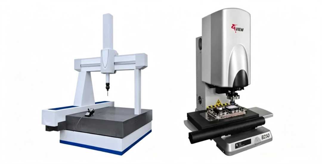
2. CMM vs Optical Measurement: Key Differences
CMM and optical measurement can both support precision dimensional inspection, but they collect data differently and are better suited to different types of features.
| Faktor | Tactile CMM | Optical Measurement |
| Measurement Method | Physical probe contact | Non-contact imaging, laser, or structured light |
| Data Density | Targeted points or scanning paths | Dense surface data across visible geometry |
| Feature Access | Strong for reachable bores, datums, steps, and internal features | Requires clear line of sight to the measured surface |
| Surface Sensitivity | Less affected by reflectivity or transparency | Can be affected by reflective, transparent, or low-contrast surfaces |
| Part Contact | Probe physically contacts the part | No mechanical contact |
| Typical Strength | Datum-related features, internal geometry, targeted dimensional inspection | Profiles, freeform surfaces, warpage, and large-area comparison |
| Inspection Speed | Efficient for selected features, but slower for dense surface coverage | Often faster when large visible areas need to be captured |
| Measurement Planning | Probe access and path must be considered | Viewing angle, surface visibility, and scan coverage must be considered |
Neither method is automatically more accurate for every part. The useful question is whether the measurement system can access the feature and achieve enough measurement capability for the required tolerance.
3. Accuracy, Measurement Uncertainty, and Traceability
Accuracy should not be judged by the measurement technology alone. Both tactile CMM and optical systems can provide traceable dimensional data when they are properly calibrated and used within their verified measurement capability.
Measurement Uncertainty Matters More Than the Sensor Type
A measurement result is useful only when its uncertainty is small enough relative to the tolerance being inspected.
For tight dimensions or GD&T requirements, the measurement plan should consider the machine specification, sensor, measuring volume, feature geometry, environmental conditions, and Inspektion strategy. A high-resolution optical system is not automatically suitable for every tight tolerance, just as a CMM is not automatically the best choice for every feature.
GD&T and Datum-Based Inspection
Tactile CMM is widely used for datum-related features such as position, perpendicularity, flatness, and bore relationships because it provides controlled 3D coordinate measurement and good access to many mechanical features.
Optical systems can also evaluate CAD alignment, datum systems, profile, form, and other GD&T characteristics when the system and measurement strategy are capable of doing so. The limitation is not that optical measurement cannot perform GD&T, but whether the feature can be seen clearly and measured with sufficient uncertainty.
Traceability and FAI
Both methods can support traceable inspection when the equipment is calibrated and the measurement process meets the applicable quality requirements.
First Article Inspection does not universally require CMM measurement. The selected method should be capable of verifying the drawing requirement and accepted by the relevant customer, specification, or quality system.
The key question is therefore not whether CMM or optical measurement is inherently more authoritative. It is whether the selected system can verify the required feature with enough confidence for the tolerance being inspected.
4. Geometry and Feature Accessibility
Part geometry often has a direct effect on which measurement method is practical.
Internal and Recessed Features
Tactile CMM is well suited to many internal features that can be physically reached by the probe, including bores, steps, pockets, and datum surfaces inside a part.
Access still depends on stylus length, probe size, approach angle, and available clearance, so deep or narrow geometry may require a different probe configuration or multiple orientations.
Line-of-Sight Limits in Optical Measurement
Optical systems need a clear view of the surface being measured. Deep pockets, undercuts, overhangs, and hidden internal features can create occluded areas that cannot be captured from a single direction.
Additional views or repositioning can extend coverage, but they also add alignment and setup work.
For open external geometry, optical measurement can capture large areas efficiently. For hidden or enclosed features, tactile probing is often the more practical option when sufficient physical access is available.
5. Surface Condition and Part Sensitivity
Surface condition and part stiffness can strongly influence which measurement method is easier to use reliably.
Contact Force and Delicate Parts
Tactile CMM measurement applies a small probing force to the part. For rigid metal components, this is usually not a problem, but very thin walls, flexible features, soft materials, or sensitive finished surfaces may require more careful probing strategies.
Low-force probing can reduce this risk, but non-contact measurement may still be preferable when even small deformation or surface marking could affect the result.
Optical Measurement and Surface Behavior
Optical systems avoid mechanical contact, which makes them useful for delicate, thin, or appearance-critical parts.
Their limitation is that measurement quality depends on how the surface interacts with light. Highly reflective, transparent, translucent, or very low-contrast surfaces can make data capture more difficult and may introduce noise or missing areas.
Additional viewing angles or surface preparation may improve the result, but they also add setup and processing steps.
The practical difference is straightforward: tactile measurement needs physical access without disturbing the part, while optical measurement needs a surface that can be captured clearly and consistently.
6. Measurement Speed, Data Density, and Automation
Measurement speed depends not only on the sensor, but also on how much data is needed and how the inspection routine is programmed.
Targeted Measurement with CMM
Tactile CMM is efficient when only selected dimensions, datums, bores, or GD&T features need to be verified. Once the program is established, the same inspection routine can be repeated consistently across production batches.
More complex parts may require additional probe paths, stylus changes, or collision checks, which can increase programming and cycle time.
Full-Field Data with Optical Measurement
Optical systems can capture dense surface data across large visible areas in a relatively short time. This is useful for profile comparison, warpage analysis, freeform surfaces, and parts where many surface points need to be evaluated at once.
The overall cycle still depends on part positioning, number of views, alignment, surface preparation, and data processing.
Automation and Production Inspection
Both methods can be integrated into automated inspection workflows. CMM is well suited to repeatable feature-based measurement, while optical systems can be advantageous when fast full-field coverage is more important.
The better option depends on whether the inspection plan needs a small number of critical measurements or dense dimensional information across a larger portion of the part.
7. When to Use CMM, Optical, or Hybrid Inspection
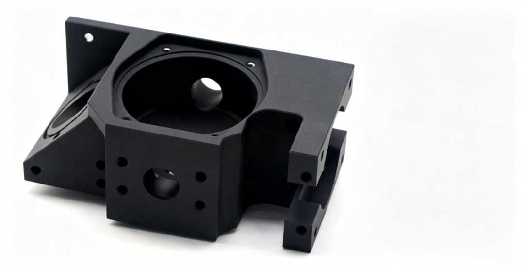
The choice becomes easier when the inspection plan is built around the features that actually need to be measured.
Use CMM When
Tactile CMM is a strong choice for tight datum-related dimensions, bores, internal steps, and other features that require controlled 3D coordinate measurement and can be reached by the probe.
It is also useful when the inspection plan focuses on a limited number of critical features rather than full-surface coverage.
Use Optical Measurement When
Optical measurement is well suited to open external geometry, profiles, freeform surfaces, warpage, and parts where a large amount of surface data needs to be collected quickly.
It is especially useful when physical contact should be minimized, provided the surface can be captured reliably by the optical system.
Use Both When the Part Has Mixed Inspection Needs
Some parts combine internal or datum-critical features with large visible surfaces. In these cases, a hybrid inspection plan can assign each feature to the method that measures it more effectively.
For example, tactile CMM may be used for bores and datum relationships, while optical measurement captures the external profile or surface deviation.
The goal is not to use both systems by default, but to avoid forcing one method to inspect features it is poorly suited to measure.
Abschluss
CMM and optical measurement are suited to different inspection tasks. The better choice depends on whether the feature requires tactile access, dense surface data, non-contact measurement, or tighter control of measurement uncertainty.
For precision machined parts, Beska supports dimensional inspection with CMM and other measurement equipment, with inspection methods selected according to the drawing and critical features.
 German
 English
 Hebrew
 Turkish
 French
 Russian
 Spanish
 Portuguese