


Inside every automotive transmission, an involute spline connects the clutch hub to the input shaft and transmits full engine torque while allowing the clutch to slide on and off the shaft under load. That combination of high torque capacity, precise rotational alignment, and controlled axial movement is something a single keyway cannot achieve. The spline’s multiple teeth share the load, self-center the hub, and permit engagement and disengagement that a keyed connection simply cannot handle.
This guide covers what splined shafts are and how they differ from keyed connections, the three main spline types, the design parameters that change what happens on the machine floor, how splines are machined, three real parts where splines solve specific problems, and when a spline is not the right choice.
1. What Are Splined Shafts?
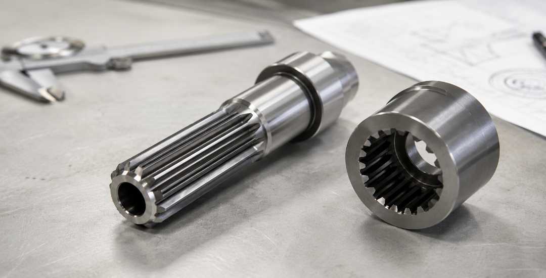
A splined shaft uses multiple teeth machined along its outer surface to engage with internal grooves in a mating component. The teeth and grooves form a positive mechanical connection that transmits torque without relying on friction or a single shear plane. This multi-tooth engagement is what gives splined shafts their advantage over simpler connection methods.
Spline vs Keyed Shaft: Why the Difference Matters
A keyed shaft uses one rectangular key inserted into a slot on the shaft and a matching slot in the hub. The key carries the entire torsional load on its single contact surface. A spline distributes that same load across all its teeth at once. That difference shows up in three places: torque capacity (a spline handles more because the load is shared), fatigue life (multiple contact points reduce local stress), and alignment (spline teeth self-center the hub, while a key may allow slight rotational clearance depending on fit and wear). For high-torque or high-speed applications, the spline is the standard choice. For low-cost, low-load situations, a keyed shaft is simpler and cheaper.
2. Types of Splined Shafts
Three spline profiles dominate industrial use. Each has a distinct tooth geometry that affects how the load is carried, how the part is machined, and what tolerances are achievable.
| Type | Tooth Profile | Typical Use | Manufacturing Note |
| Straight-sided (parallel) | Flat, parallel tooth flanks | General power transmission, agricultural equipment | Simplest to machine; tooth geometry is defined by width and spacing, not by curve generation |
| Involute | Curved tooth profile (same geometry as gears) | Automotive transmissions, gearboxes, high-torque drives | Most common in production; self-centering under load; requires hobbing or shaping for accurate profile |
| Serrated | V-shaped or triangular teeth | Steering columns, precision positioning, small instrument shafts | High radial locking force; typically broached; limited torque capacity compared to involute designs |
The involute profile is the default choice for most engineered applications because it self-centers the mating hub under load and follows the same manufacturing standards as spur gears. Straight-sided splines are used when cost matters more than precision. Serrated splines appear where angular positioning accuracy outweighs torque requirements.
3. Design Parameters That Change the Manufacturing Outcome
When engineers design a splined connection, they work through six interdependent parameters: tooth profile, pressure angle, tooth count relative to shaft diameter, fit classification, base material, and whether post-machining heat treatment is needed. Changing one often forces a revision of another. The sections below cover the three parameters that most directly affect the machining outcome.
Pressure Angle
The pressure angle defines the angle between the tooth flank and a line tangent to the pitch circle. The standard involute spline uses a thirty-degree pressure angle,which is the most common pressure angle for many involute spline standards, although other values are also used depending on the application. A higher pressure angle increases radial force on the hub, which can improve self-centering but also increases tooth root stress. From a machining standpoint, the pressure angle determines the hob profile and the inspection method. A thirty-degree angle is well-supported by standard tooling and measurement equipment. Non-standard angles require custom hobs and more complex verification, which adds cost and lead time.Standard pressure angles simplify tooling selection and inspection, while non-standard profiles increase manufacturing cost.
Tooth Count and Diameter
More teeth spread the load across more contact points, reducing stress per tooth. Fewer teeth simplify machining and leave more room at the tooth root, improving fatigue resistance. The trade-off is load sharing versus root strength. Tooth count follows the torque requirement and available shaft diameter. Too many teeth on a small-diameter shaft leaves insufficient root depth and it fails under cyclic loading.
Small-diameter splines bring manufacturing challenges easy to miss on a print. Tight tooth spacing makes burr removal difficult — standard deburring tools cannot reach between the teeth. Thin tooth sections distort during heat treatment, pushing the profile out of tolerance and requiring a corrective grind. Inspection is harder too: small-diameter splines often need CMM or optical measurement rather than standard go/no-go gauges. These factors add cost and lead time the torque requirement alone does not justify.
Fit Classifications
Splined connections use three fit types: sliding fit allows axial movement under load (clutches, disconnect mechanisms), transitional fit allows movement only without load (gearbox shafts), and fixed fit locks the hub to the shaft (permanently coupled drives). The fit classification sets the tolerance zone on tooth thickness and space width, which determines whether the part can ship directly from the hob or needs a post-hob grind. A sliding fit specified where a fixed fit is needed causes axial drift. A fixed fit where the design requires disengagement makes the assembly unserviceable.
In manufacturing terms, the fit class directly drives process selection, grinding requirements, and inspection cost. A fixed fit may be producible straight from the hob. A sliding fit may need a post-hob grind to hold the tighter tooth thickness tolerance. Transitional fits typically demand in-process measurement rather than final inspection alone. The tighter the fit, the higher the cost of producing and verifying it.
4. How Splined Shafts Are Machined
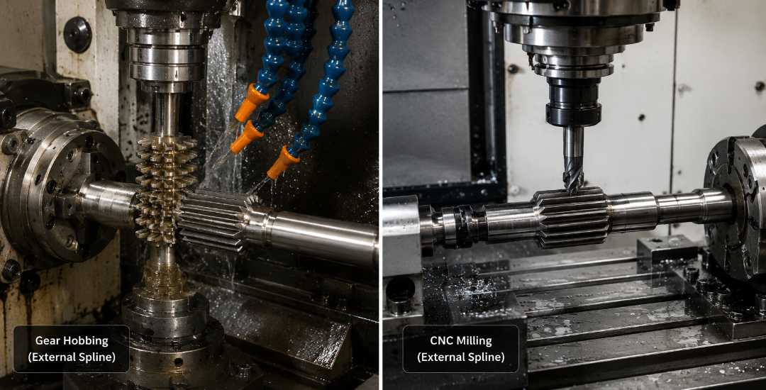
The machining method depends on the tooth profile, production volume, and tolerance class. Three processes cover most production scenarios: broaching, hobbing, and CNC milling. Three additional methods apply when the application demands tighter tolerances or higher volume.
Spline grinding corrects heat-treatment distortion and meets tolerances too tight for hobbing alone. Gear shaping generates internal involute splines that cannot be broached, such as blind holes or stepped bores, using a reciprocating cutter. Spline rolling cold-forms teeth by displacing rather than cutting material, producing work-hardened teeth with no chip waste. The process is fast but limited to external splines on ductile materials at high volume.
Broaching
Broaching pulls a multi-tooth cutting tool through the workpiece in a single pass, forming the complete spline profile. It is the fastest method for internal splines and straight-sided external splines in high-volume runs. The limitation is tool cost: a broach is custom-made to match exact spline dimensions and cannot be easily modified. Broaching is justified when production volume amortizes the tooling cost across thousands of parts.
At Beska, broaching is recommended for internal spline production runs above roughly 500 parts, where the per-part cycle time advantage pays back the broach tooling cost within a single production batch.
Hobbing
Hobbing uses a rotating cutter shaped like a worm gear to generate involute teeth progressively. The cutter and workpiece rotate in synchronized feed, each pass removing material until the full tooth profile is formed. Hobbing is standard for involute splines because the same cutter can produce different tooth counts by adjusting the feed ratio, making it practical for medium-volume production and shafts with multiple spline sections. On the shop floor, hobbing leaves a finish acceptable for most applications, but tight-tolerance fits may require a subsequent grind.
For medium-batch external involute splines, typically 50 to 500 shafts, hobbing is the preferred process at Beska because the same hob can be set up for different tooth counts within the same spline family, keeping changeover time low.
CNC-Fräsen
CNC-Fräsen cuts each tooth individually using a shaped end mill that follows the spline profile path. This method is slower than hobbing or broaching but offers full flexibility: tooth count, profile, pressure angle, and length can all be changed by updating the CNC program. CNC milling is the practical choice for prototype runs, low-volume orders, and shafts with non-standard spline geometry that no standard hob or broach can produce. The trade-off is cycle time and surface finish, which typically require more passes and finer tooling than a generated process.
Beska uses CNC milling for prototype splined shafts and for low-volume orders under roughly 30 parts, where the cost of a dedicated hob or broach cannot be justified and the flexibility of a programmable toolpath is the deciding factor.
5. Splined Shafts on Real Parts
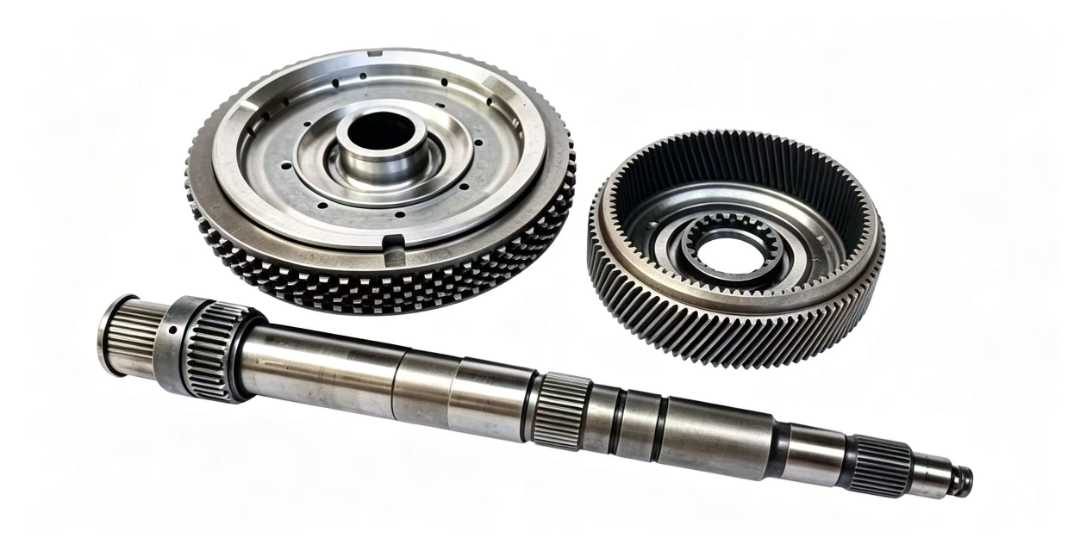
The examples below show how a specific spline type solves a specific problem on a specific component.
Transmission Input Shaft
An automotive transmission input shaft uses an involute spline to connect the torque converter or clutch hub to the shaft. The spline must transmit full engine torque under continuous cyclic loading while allowing the clutch to engage and disengage axially, which requires a sliding fit classification. The manufacturing challenge is achieving the tooth profile accuracy needed for smooth axial sliding while maintaining the torsional strength to handle peak engine torque. This typically means hobbing followed by a light grind on the tooth flanks, with spline gauge inspection to verify fit clearance.
Manufacturing focus: The post-hob grind on the tooth flanks is the cost driver. Skipping it saves money but risks axial stick-slip during clutch engagement. On a transmission shaft, that risk is not worth the saving.
PTO Drive Shaft
A power take-off shaft on agricultural equipment uses a straight-sided spline at the connection point between the tractor and the implement. The spline must handle shock loads from sudden engagement and resist contamination from field debris, which makes tooth root strength and surface hardness more important than profile precision. Induction hardening of the spline teeth is standard practice. The simpler straight-sided profile keeps machining cost down and allows field replacement with readily available PTO shaft components.
Manufacturing focus: Induction hardening is the critical step. If case depth is too shallow, the tooth surface spalls under shock. If too deep, the core becomes brittle and the root loses toughness. Post-hardening hardness testing across the tooth cross-section matters more than profile inspection on this part.
Steering Column Shaft
A steering column uses a serrated spline to connect the steering wheel to the rack mechanism. The serrated profile provides high angular positioning accuracy and strong radial locking, which prevents rotational play between the wheel and the steering input. The manufacturing process is typically broaching on an internal hub and roll forming or milling on the shaft, with tight dimensional control on tooth spacing to eliminate perceptible steering backlash.
Manufacturing focus: Tooth spacing accuracy directly correlates with steering feel. A few microns of spacing variation translates into angular play at the steering wheel rim. CMM inspection of tooth-to-tooth spacing is typically required rather than a standard go/no-go spline gauge.
6. When Not to Specify a Spline
A spline is not always the right answer. Four situations where a simpler connection makes more sense:
Low-torque applications. When the transmitted torque is light enough that a single key can carry the load without fatigue risk, a keyed shaft is simpler, cheaper, and faster to produce. Adding a spline to a low-load connection increases machining cost without delivering a proportional benefit.
Small shaft diameters. On very small shaft diameters, often around 10 mm or below depending on torque and material, the tooth root depth on a spline becomes so shallow that fatigue life drops sharply. A keyway or a press fit with an adhesive bond is more reliable at these diameters.
Permanently fixed assemblies. If the hub never needs to slide, disengage, or be removed for service, a shrink fit or a keyed connection with a retaining nut achieves the same result with less machining complexity. The spline’s ability to permit axial movement is wasted in a fixed assembly.
Very low production volumes. Broaching and hobbing both require dedicated tooling that must be amortized across a production run. For a one-off or a handful of parts, CNC milling the spline is possible but expensive. A keyed shaft machined in a single setup is often the more practical choice for prototype or ultra-low-volume orders.
In these situations, the additional cost of a spline often provides little practical benefit.
Abschluss
A splined connection is a deliberate engineering choice, not a default. It adds machining complexity, dedicated tooling requirements, and tighter tolerance control compared to a keyed shaft. The payoff is a connection that handles more torque, holds rotational alignment without backlash, and can engage or disengage under load. When those capabilities are not needed, the extra cost and processing steps are wasted. The key to specifying a spline correctly is knowing which of its advantages the application actually requires and which are irrelevant, then selecting the tooth profile, fit class, and manufacturing process that deliver only what is necessary.
Bei Beska, spline specification reviews start with four questions: the tooth profile and pressure angle, the fit class and whether a post-hob grind is required, the base material and post-machining heat treatment, and the production volume that decides between CNC milling, hobbing, or broaching. Kontaktieren Sie uns to discuss your splined shaft requirements, from prototype to production.
Deeper into Our Resources
Damit Sie einige aufschlussreiche Lektüre finden, haben wir eine Liste mit empfohlenen Artikeln speziell für Sie zusammengestellt:
 German
 English
 Hebrew
 Turkish
 French
 Russian
 Spanish
 Portuguese